
Synergix / Specialist vehicle guides
HIAB crane
vehicles.
A lorry that carries the load and brings its own crane. Choose from rigid flatbeds, wagon-and-drag combinations and crane-equipped artics, with the lift planned around your goods and site.
Move suitable goods where a site forklift or loading bay is unavailable.
Compare rigid, drawbar and articulated arrangements in one guide.
Match the crane, load and working space before the job is agreed.
The full HIAB range
Choose your HIAB.
Explore 18t and 26t rigid HIABs, front- and rear-crane wagon and drag, and three- and four-axle crane tractors with their flatbed combinations.
Select a vehicle for its full guide. Swipe on phones or use the stationary list.
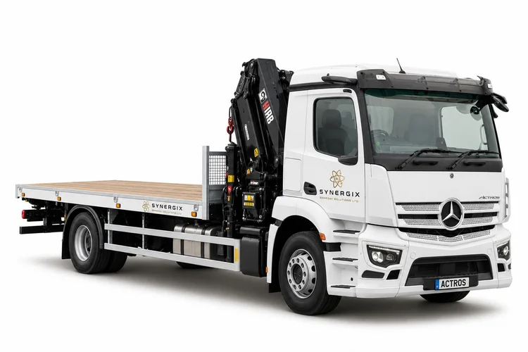 18t flatbed HIABRead this vehicle guide ↓
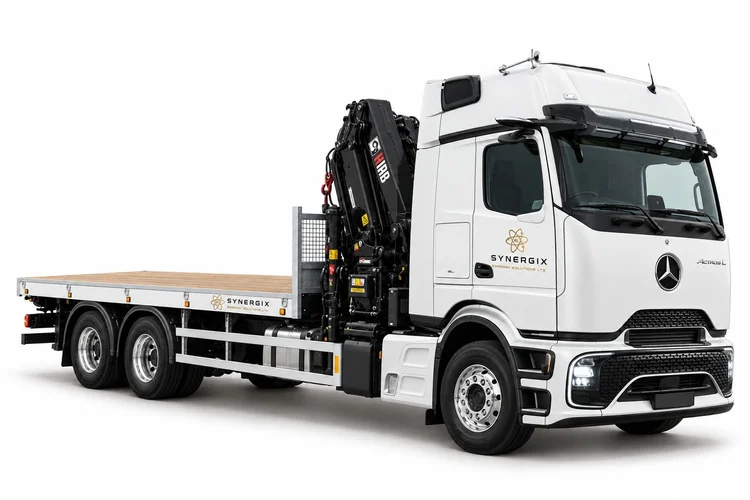 26t flatbed HIABRead this vehicle guide ↓
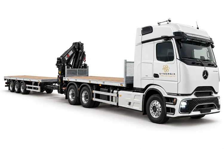 Wagon & drag, rear HIABRead this vehicle guide ↓
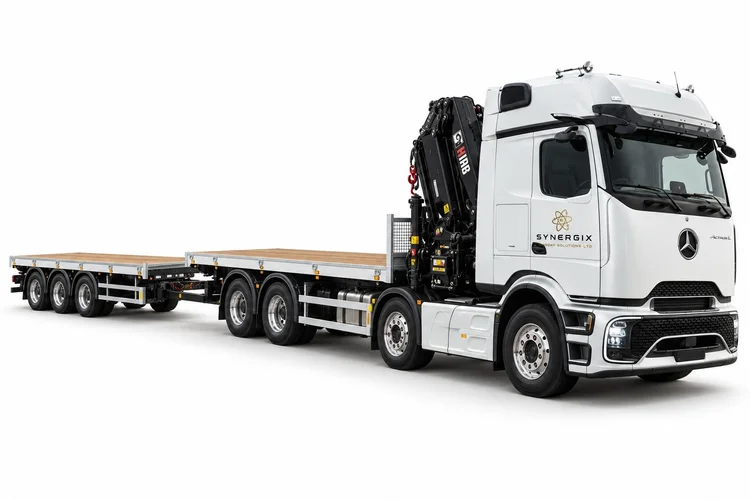 Wagon & drag, front HIABRead this vehicle guide ↓
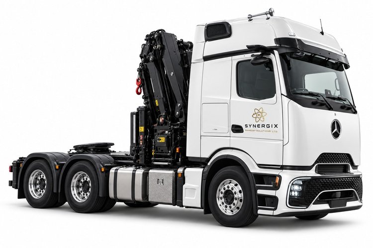 Three-axle HIAB tractorRead this vehicle guide ↓
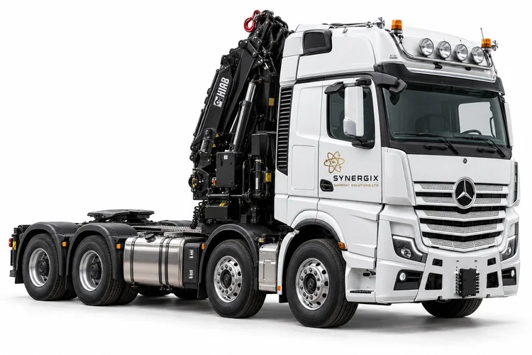 Four-axle heavy HIAB tractorRead this vehicle guide ↓
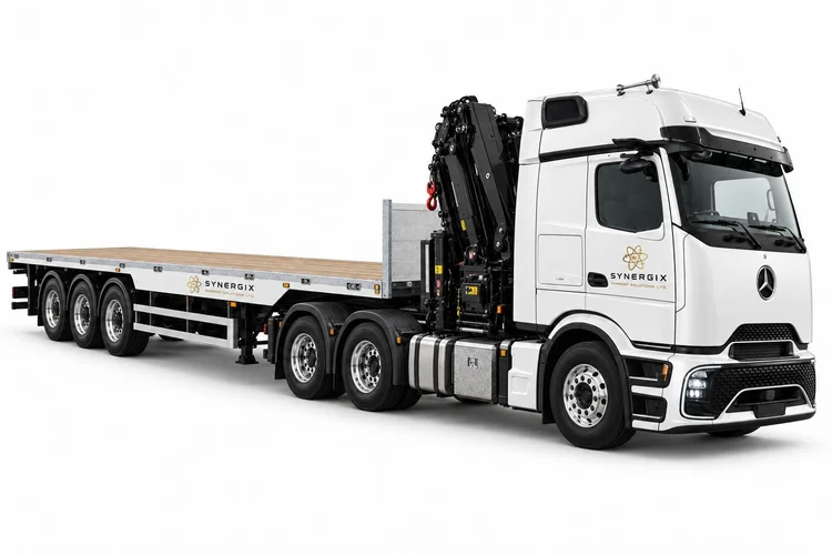 HIAB artic & flatbedRead this vehicle guide ↓
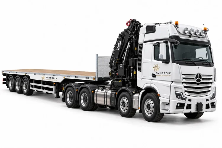 Heavy HIAB artic & flatbedRead this vehicle guide ↓
Stationary list of all eight HIAB vehicle guides
Catalogue illustrations show vehicle arrangements, not a promised make, model, lift rating or available vehicle on your date. Tractor-only pictures explain the tractor; coupled pictures show the complete transport arrangement.
Dimensions and payload
The load must fit.
The weights must work.
The usable deck length and width, loading height and freight allowance depend on the body and crane installation. A rigid, drawbar trailer and semitrailer have different layouts. We confirm the allocated vehicle’s measurements against the complete load, including packaging, lifting points, supports and projections.
Send dimensions and weight together.
Give the packed length, width and height of each item, its complete weight and quantity. For a container or cabin, include contents and any equipment still inside. A photograph helps identify the shape and lifting points; it does not replace a reliable weight.
We also need the vehicle approach, the proposed crane position and where the goods must finish. Space to drive in does not prove there is space to deploy the crane.
| Arrangement | Loading dimensions | Capacity and handling |
|---|---|---|
| 18t / 26t rigid HIAB | Usable deck length/width, deck height, headboard and crane intrusion. | Actual ready-to-work mass, remaining freight allowance, axle loads and crane chart. |
| Front / rear HIAB wagon and drag | Truck and trailer measured separately, plus coupling and full operating space. | Each platform’s ratings, loading sequence and crane radius to both decks. |
| Three / four-axle crane tractor | No cargo deck on the uncoupled tractor; identify the complete trailer arrangement. | Tractor, crane and trailer compatibility, axle distribution and approved stability configuration. |
| Artic / heavy artic with flatbed | Actual usable trailer deck, loaded height, support points and route envelope. | Complete combination weights and crane capacity at every required picking/placing radius. |
18t and 26t describe vehicle weight categories. They are not promises to carry or lift that mass. Standard-body payload and pallet figures cannot be applied to a crane-equipped vehicle unchanged.
Calculate freight from the ready-to-work vehicle
Start with the relevant gross or combination limit and the actual vehicle mass in its working condition. For a crane vehicle, that includes the installed crane and subframe, body, supports, hydraulic equipment, carried accessories, fuel, people and any trailer included in the measurement. Whatever is already present in a measured ready-to-work figure must not be subtracted again.
A worked example helps show the distinction: an assumed 26,000 kg gross limit minus an assumed 17,500 kg ready-to-work vehicle leaves 8,500 kg by gross-weight subtraction. These assumed values illustrate the calculation and are not a specification for a supplied vehicle. Individual axles, deck/support ratings and the crane may impose lower limits. The 8,500 kg is not an 8,500 kg lifting promise.
| Weight | What belongs in it | Why it matters |
|---|---|---|
| Individual lifted item | Machine or goods plus contents and everything remaining attached during the lift. | The crane handles each complete suspended load. |
| Transport consignment | All goods, packaging, pallets, stillages, transport bearers and any carried removable equipment. | The vehicle carries all of it, even when an item is lifted separately. |
| Rigging and attachments | The relevant hook block, slings, shackles, lifting beam and attachments, treated as the actual chart requires. | Equipment hanging from the crane uses capacity as well as the goods. |
A long load can fit the deck and still need different handling
Packed dimensions include projections, machinery feet, container corners, wrapping and support materials. The loading space must accommodate the load in a supported and restrained position. For a wagon and drag, record each deck separately. For an artic, use the actual semitrailer’s clear deck, not a general enclosed-trailer figure copied from another guide.
Pallet counts only help for suitable palletised cargo. UK standard bases are commonly 1,200 × 1,000 mm and Euro bases 1,200 × 800 mm, but the loaded footprint may be larger. HIAB deck counts depend on crane intrusion, deck geometry, supports, weight distribution and rigging access. We do not publish a universal pallet count for these eight different installations.
Axle distribution changes when goods move
A crane near the cab, a rear crane, trailer drawbar load and semitrailer kingpin load act at different positions. The loaded vehicle has to remain within each applicable axle/group limit as well as its total. Unloading one item changes that balance; it does not necessarily reduce every axle load equally.
A dense machine on small feet also imposes concentrated loads on the body. Its support arrangement must carry and distribute those forces without damaging the deck or machine. Send foot spacing, skid/bearer details and drawings for unusual loads so the body and lifting methods can be selected together.
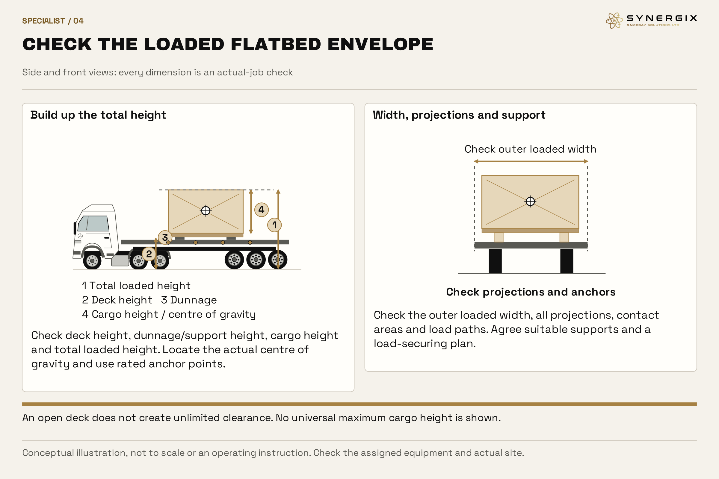

The 26,000 − 17,500 = 8,500 kg example is hypothetical arithmetic, not a fleet payload, axle check or lift approval.
Open full-size desktop diagram · Open full-size mobile diagram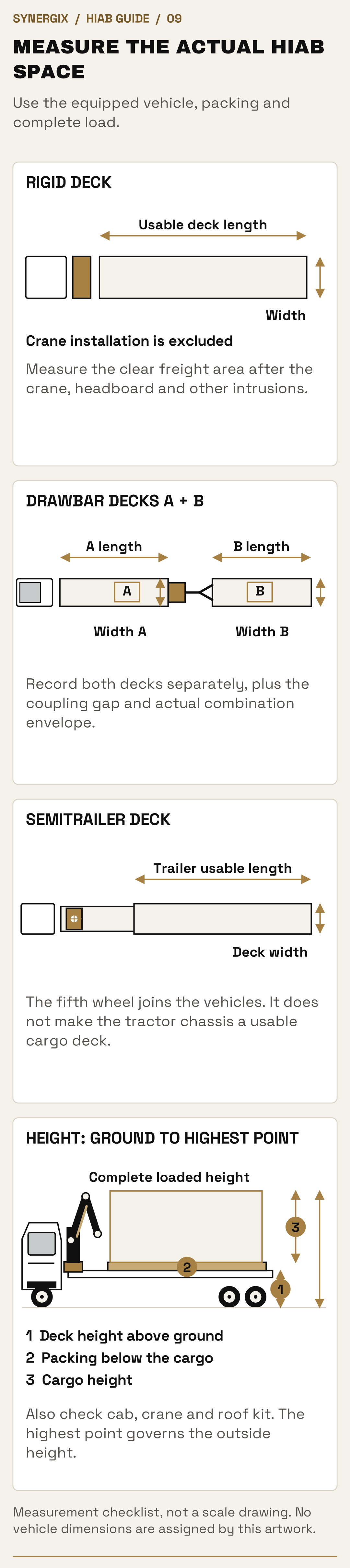
Measurement checklist, not a scale drawing. No vehicle dimensions are assigned by this artwork.
Open full-size desktop diagram · Open full-size mobile diagramChoose the arrangement
What changes between
HIAB vehicles?
Choose around the job the equipment must complete. These comparisons explain the difference between arrangements; the quoted vehicle and crane specification establish the actual figures.
| Comparison | Useful difference | What can change the choice |
|---|---|---|
| 18t versus 26t rigid | A different chassis/body/crane installation while retaining one rigid deck. | Complete freight allowance, deck and required lift at radius, not the gross-weight number alone. |
| Rear versus front wagon-and-drag crane | Rear crane begins nearer the interface between truck and trailer; front crane begins behind the cab. | Radius to each item on both decks, structural installation, trailer position and unloading order. |
| Three-axle versus four-axle crane tractor | Carrier mass distribution and structure can accommodate a different scale of installed crane. | Actual lifting duty, chassis/subframe/support design, fifth-wheel allowance and road access. |
| Tractor alone versus coupled flatbed | The coupled trailer provides the normal cargo deck; the tractor-only picture explains the crane unit. | Approved coupled/uncoupled lifting setup and how freight will be supplied to the crane. |
| Wagon and drag versus artic flatbed | Two separate load platforms versus one semitrailer platform. | Individual item lengths, ability to split the freight, manoeuvring, crane reach and support. |
| Onboard crane versus separate site lifting | Combining carriage and lifting can remove the need for suitable equipment at the receiving site. | Existing site equipment, lift complexity, access, total mobilisation and complete job cost. |
HIAB configuration 01 / 08
18t flatbed HIAB
Rigid / two axles
A compact rigid option within the HIAB range. An open loading deck and a behind-cab crane combine transport and lifting.
A useful starting point for a single-deck movement where a smaller rigid can carry the goods and complete the required lifts. Compare the deck, freight allowance and crane duty together.
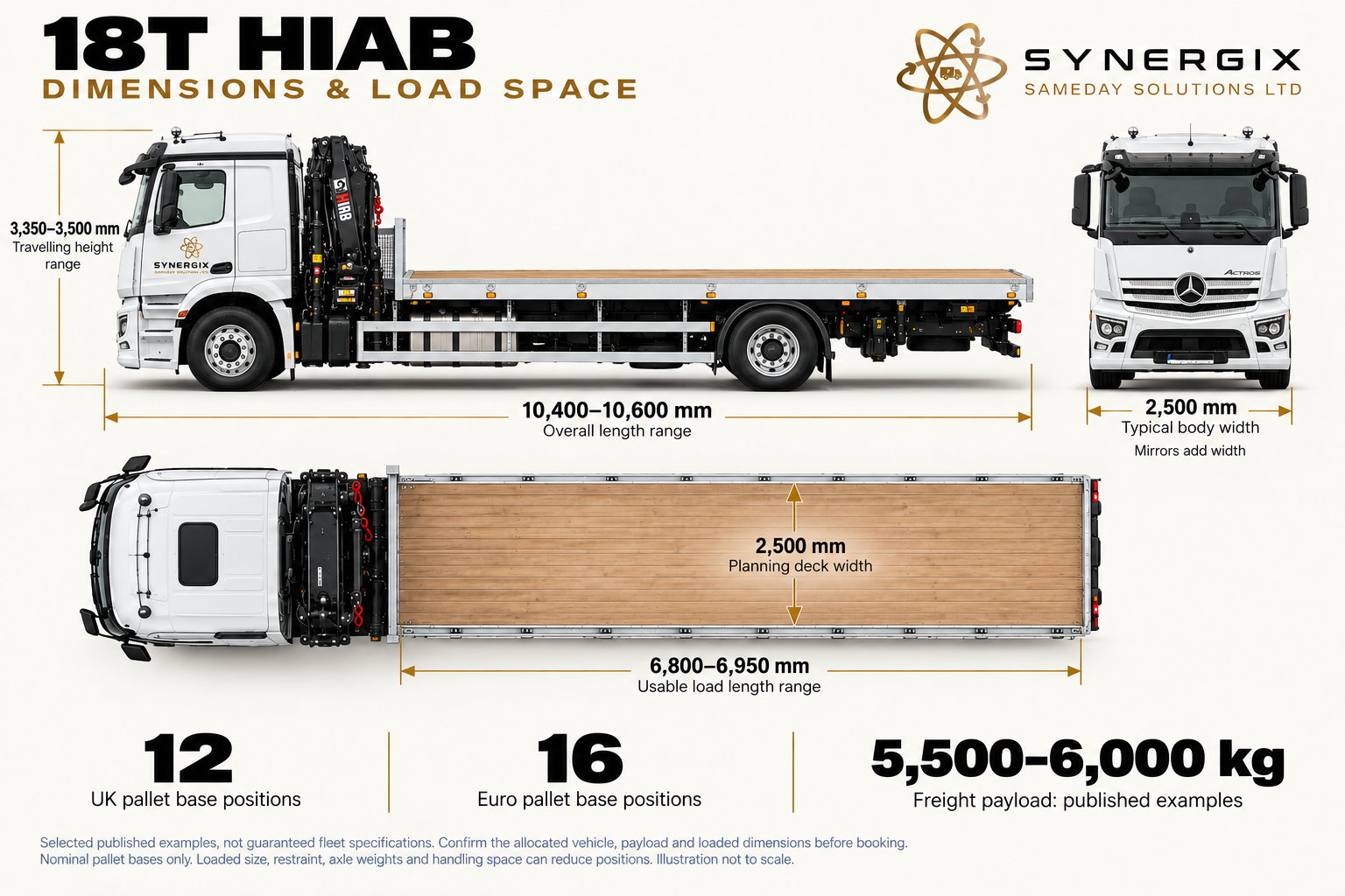
18 T HIAB dimensions
Published planning examples. The actual vehicle, equipment, load distribution and access must be checked for your booking.
Open the full-size diagramDimensions and planning figures in text
overall Length: 10,400–10,600 mm; travelling Height: 3,350–3,500 mm; body Width: 2,500 mm; mirrors additional; load Length: 6,800–6,950 mm; load Width: 2,500 mm; payload: 5,500–6,000 kg published examples. 6,800 × 2,500 mm deck. UK 12 (6 × 2), Euro 16 (8 × 2). Nominal length margins 800 mm and 400 mm.
Selected published 18 t examples; actual allocated carrier and crane vary.
Published example sources:
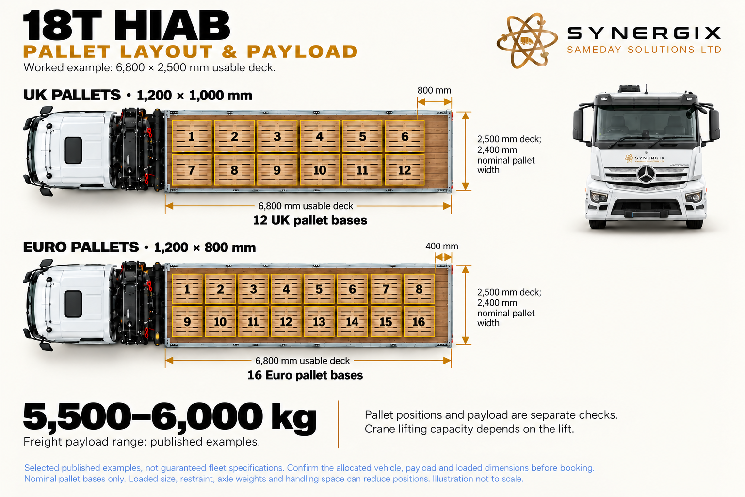
18 T HIAB pallet layout
Published planning examples. The actual vehicle, equipment, load distribution and access must be checked for your booking.
Open the full-size diagramDimensions and planning figures in text
overall Length: 10,400–10,600 mm; travelling Height: 3,350–3,500 mm; body Width: 2,500 mm; mirrors additional; load Length: 6,800–6,950 mm; load Width: 2,500 mm; payload: 5,500–6,000 kg published examples. 6,800 × 2,500 mm deck. UK 12 (6 × 2), Euro 16 (8 × 2). Nominal length margins 800 mm and 400 mm.
Selected published 18 t examples; actual allocated carrier and crane vary.
Published example sources:
A rigid lorry with transport and lifting on one chassis
The 18t flatbed HIAB brings a cab, two-axle chassis, open load deck and behind-cab loader crane together. The goods travel behind the crane and can be lifted off to an assessed position. There is no separate trailer to couple or position, which can simplify a single collection and delivery where the load fits one rigid deck.
Its useful role is a smaller rigid crane delivery, rather than buying the longest deck or heaviest lifting installation by default. Suitable packaged machinery, building materials and equipment can be considered where their individual weights, lifting arrangement and placing radius suit the allocated crane. A comparatively modest load close beside the vehicle is a different brief from the same load behind a wall.
What the smaller chassis changes
A shorter rigid arrangement can be easier to accommodate than a complete artic or drawbar combination, but axle count alone does not establish turning circle, wheelbase or access width. The site still needs room for the lorry, deployed supports and the load path. A narrow driveway which admits the cab may provide nowhere for the stabilisers to stand.
The crane, subframe, hydraulic equipment, support pads and carried lifting gear all form part of the vehicle mass. That leaves less freight allowance than an otherwise comparable plain flatbed. A compact vehicle may run out of road payload or deck length before it runs out of close-in crane capability. Those are separate reasons to move to another arrangement.
Loading, unloading and choosing the next size
For a behind-cab installation, the distance from the slew centre to the far end of the deck matters. The loading plan must let the crane reach each lifting point and leave access for rigging. A load that can be craned onto the front of the deck is not automatically reachable after it has been positioned farther back.
Compare the 26t rigid when the single-deck job needs a different freight allowance, deck layout or crane duty. Compare a plain flatbed with suitable site cranes or forklifts at both ends if an onboard crane brings no benefit. The smaller HIAB remains worthwhile when it meets the complete requirement and avoids paying for unnecessary equipment.
Illustrative booking
A workshop needs one machine moved to a yard with no forklift. Send the packed machine dimensions, reliable weight, approved lifting points and a photograph of the final position. The question is whether the actual 18t rigid can carry it and complete both lifts, rather than whether the machine is below 18 tonnes.
HIAB configuration 02 / 08
26t flatbed HIAB
Rigid / three axles
A larger rigid flatbed with a behind-cab loader crane. It keeps the cab, crane and cargo deck on one vehicle.
Compare it with the 18t option where more deck space or freight capacity is needed. The crane installation changes usable payload; standard 26t flatbed figures are not transferable.
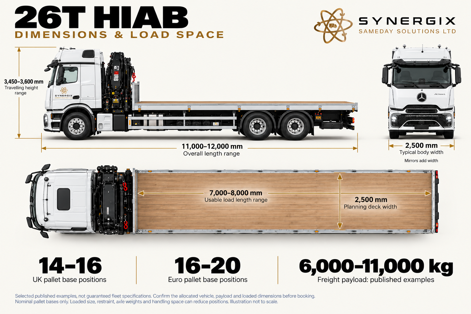
26 T HIAB dimensions
Published planning examples. The actual vehicle, equipment, load distribution and access must be checked for your booking.
Open the full-size diagramDimensions and planning figures in text
overall Length: 11,000–12,000 mm; travelling Height: 3,450–3,600 mm; body Width: 2,500 mm; mirrors additional; load Length: 7,000–8,000 mm; load Width: 2,500 mm; payload: 6,000–11,000 kg published examples. 8,000 × 2,500 mm deck. UK 16 (8 × 2), Euro 20 (10 × 2). Both regular layouts have zero nominal length margin.
Selected published 26 t examples; more pallet positions do not establish a freight allowance.
Published example sources:
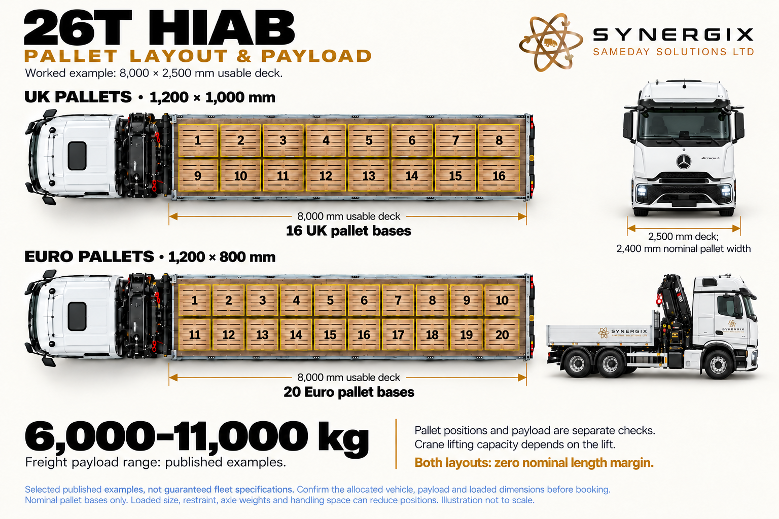
26 T HIAB pallet layout
Published planning examples. The actual vehicle, equipment, load distribution and access must be checked for your booking.
Open the full-size diagramDimensions and planning figures in text
overall Length: 11,000–12,000 mm; travelling Height: 3,450–3,600 mm; body Width: 2,500 mm; mirrors additional; load Length: 7,000–8,000 mm; load Width: 2,500 mm; payload: 6,000–11,000 kg published examples. 8,000 × 2,500 mm deck. UK 16 (8 × 2), Euro 20 (10 × 2). Both regular layouts have zero nominal length margin.
Selected published 26 t examples; more pallet positions do not establish a freight allowance.
Published example sources:
The three-axle rigid flatbed HIAB
The 26t rigid keeps crane, deck and cab on the same vehicle, using a three-axle chassis in the illustrated arrangement. It is an important middle ground between the smaller rigid and a combination with a separate trailer. It can provide a practical platform for a larger body or a different crane installation while retaining the simpler positioning of one rigid vehicle.
This arrangement can suit industrial equipment, supported packs, construction products and suitable containers or cabins where the actual deck and crane duty align. It is particularly worth considering when the receiving site needs crane offload but a full articulated or drawbar combination would add unnecessary length and complexity.
Why two 26t HIABs can carry very different freight
The 26t category describes gross vehicle weight. It does not define the crane, deck, ready-to-work mass or remaining freight capacity. A vehicle built around a larger crane can offer a more demanding lift while leaving less allowance for goods than a lighter-crane installation. Extra crane reach, a fly jib, winch, substantial subframe and additional supports all have mass.
The rear axle group and front axle must also remain within their relevant limits. The crane starts as a concentrated installed weight behind the cab. Freight placement then changes the axle distribution, so a total consignment which appears acceptable by subtraction can still be unsuitable in a particular position. A photograph of an empty flatbed cannot establish that distribution.
Deck length, lifting position and working sequence
Use the actual clear deck after accounting for the crane installation, headboard, tool storage and any other intrusion. Include bearers, packing and access for the lifting gear. A long steel pack and several separate machines need different arrangements even when their total mass is identical.
A behind-cab crane may need a greater radius to lift an item at the tail of the deck than one close to the crane. At delivery, its distance to the final placing point can be more significant than road capacity. On multi-stop work, the remaining freight needs an appropriate axle balance and restraint after each unloading, not just at departure.
When a larger combination helps
A wagon and drag adds a second platform for loads that divide appropriately between decks. An artic flatbed can provide a longer continuous platform. Neither automatically solves a heavier single lift. If the 26t vehicle can carry the goods but cannot lift them at the required radius, compare the crane installation and placing arrangement rather than merely asking for more trailer space.
HIAB configuration 03 / 08
Wagon & drag, rear HIAB
Wagon and drag / rear crane
A crane at the rear of the rigid works with two separate load platforms: the truck body and its drawbar trailer.
Crane position can help with access towards the trailer, but reach to each pick and placing point still needs checking. Each deck has its own dimensions and loading limits.
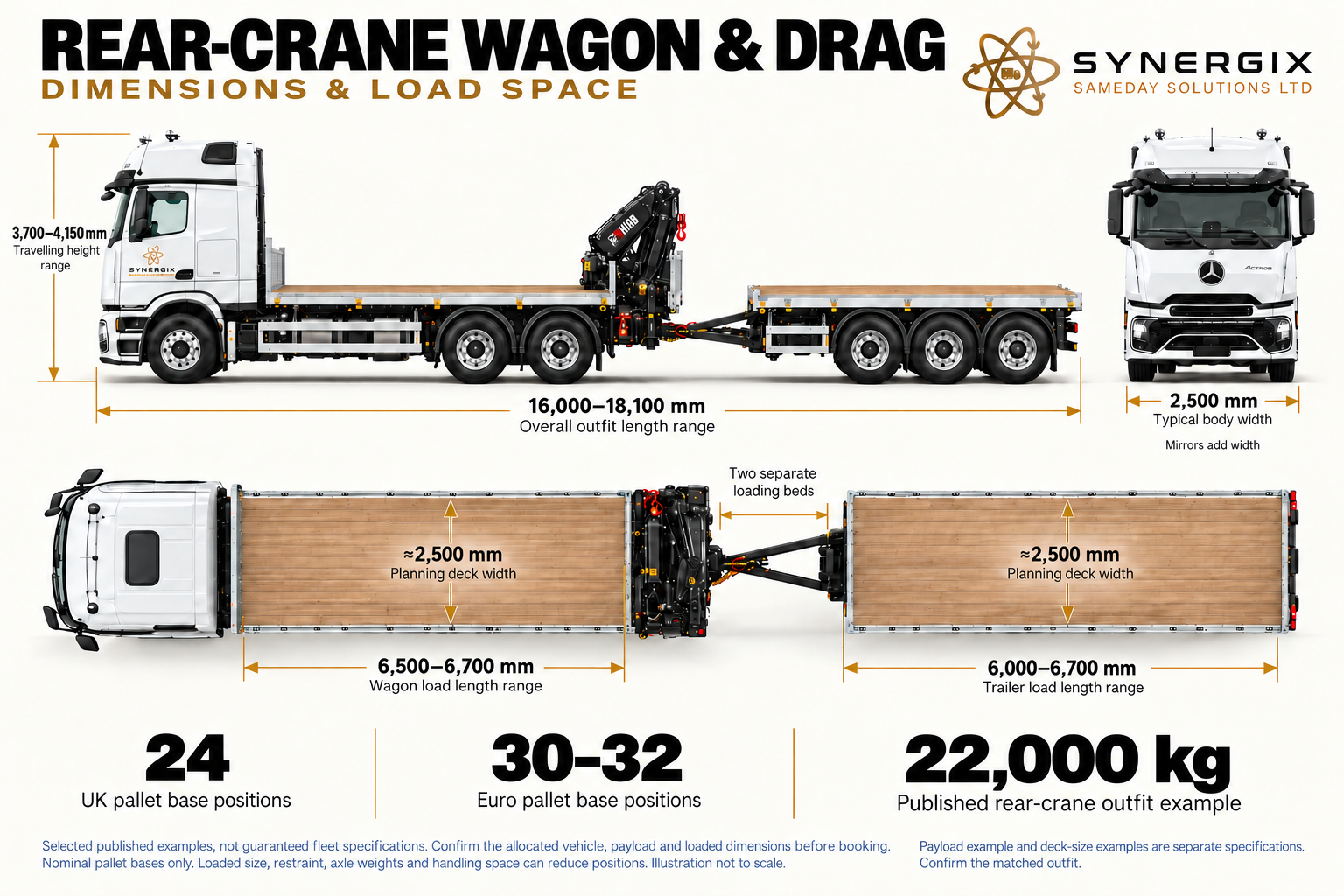
Rear-crane HIAB wagon and drag: dimensions
Published planning examples. The actual vehicle, equipment, load distribution and access must be checked for your booking.
Open the full-size diagramDimensions and planning figures in text
Complete length 16,000–18,100 mm, stowed height 3,700–4,150 mm, body width 2,500 mm. Wagon 6,500–6,700 mm, trailer 6,000–6,700 mm, deck width about 2,500 mm. Worked 6,700 mm beds give 24 UK or 32 Euro. Published rear-crane freight example 22,000 kg.
Payload and deck-size examples are separate builds. Rear crane bay and coupling are not cargo floor.
Published example sources:
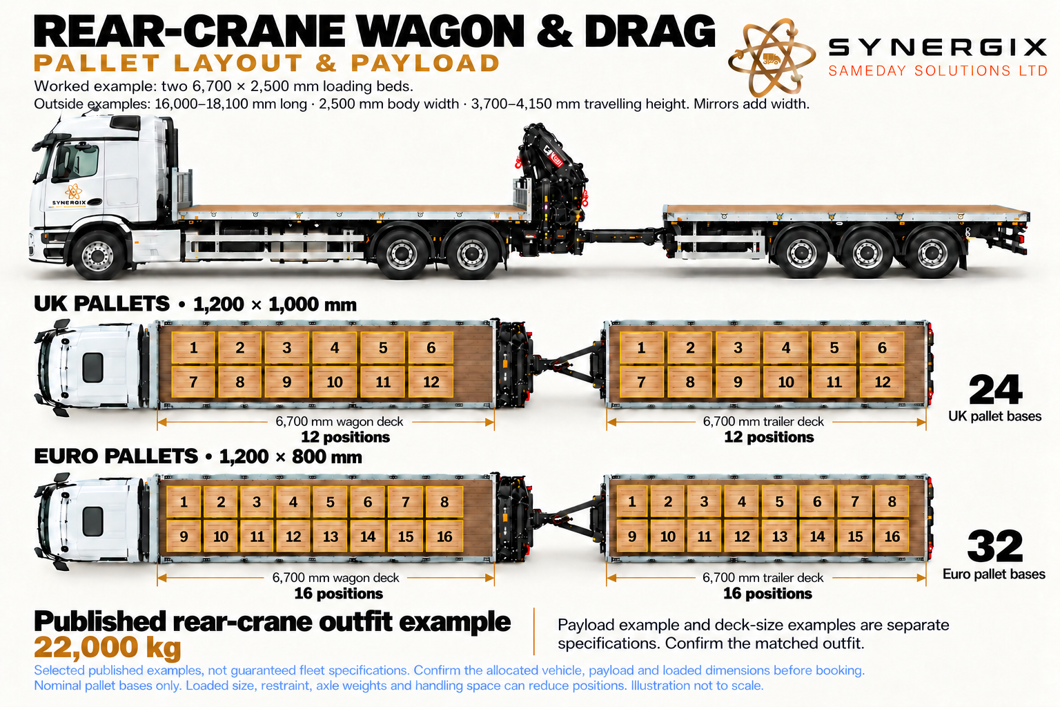
Rear-crane HIAB wagon and drag: pallet layout
Published planning examples. The actual vehicle, equipment, load distribution and access must be checked for your booking.
Open the full-size diagramDimensions and planning figures in text
Complete length 16,000–18,100 mm, stowed height 3,700–4,150 mm, body width 2,500 mm. Wagon 6,500–6,700 mm, trailer 6,000–6,700 mm, deck width about 2,500 mm. Worked 6,700 mm beds give 24 UK or 32 Euro. Published rear-crane freight example 22,000 kg.
Payload and deck-size examples are separate builds. Rear crane bay and coupling are not cargo floor.
Published example sources:
A rear crane between the working areas
This wagon-and-drag arrangement has a crane at the rear of the rigid truck and a separate drawbar trailer behind it. The crane therefore begins nearer the back of the truck deck and the front of the trailer than a behind-cab crane would. That relative position can be valuable when collecting or delivering goods carried on both platforms.
The principal benefit is two separately rated load platforms carried by one road combination. It can suit multiple cabins, containers, packs or equipment items when they divide sensibly between the decks and each lift is within the crane’s actual chart. It is not one continuous flatbed: an item cannot simply occupy the coupling gap or bridge the two moving vehicles.
Why the rear position can change the lift
Moving the crane origin towards the trailer can shorten some pick radii, particularly for loads towards the adjoining ends of the two decks. It also changes the relationship between the crane and a load at the truck’s front. The useful question is the distance from the actual slew centre to every load centre and landing point, not whether rear mounting is always better.
The trailer’s far end may still require considerable reach. The drawbar, trailer position, load height and boom geometry can obstruct a direct path. A long trailer or a second row of goods is not automatically reachable because the nearest load is. Layout, radius and the loading order are assessed together.
Truck, trailer and crane support are different systems
Road freight is shared between the rigid’s deck and the trailer’s deck. Their individual ratings, axle loads, drawbar/coupling limits and overall combination limits all matter. The weight of a rear-mounted crane also changes the rigid’s axle distribution and the loads carried through its structure. Rear mounting is a designed installation, not just moving a crane to a spare patch of deck.
During lifting, the approved stabiliser arrangement and supporting ground control the crane vehicle. Do not assume that the drawbar trailer acts as an outrigger or useful counterweight. Whether it remains connected, where it stands and any repositioning or uncoupling must follow the actual installation and planned operation.
Access, uncoupling and the unloading order
A drawbar combination needs an approach and manoeuvring plan for both vehicles. If the work requires the rigid to operate separately, a suitable trailer parking and support area is needed, along with the time and safe process for uncoupling and reconnecting. Separating the combination is not permission to abandon a loaded trailer on soft ground.
Plan which platform is loaded or emptied first and what remains aboard. The crane must still reach the next item, the road distribution must remain appropriate and people need a safe way to attach or remove lifting gear. A delivery sequence which works at an open yard can fail at the final constrained site.
Compare it with front-mounted wagon and drag
The rear arrangement can offer a useful crane position between the platforms. The front arrangement starts beside the cab and has a different reach to both decks, rear-body layout and chassis installation. For your quotation, provide a sketch showing each item’s intended deck and the landing positions. That lets us compare the working geometry rather than select a vehicle from its name.
HIAB configuration 04 / 08
Wagon & drag, front HIAB
Wagon and drag / front crane
A front-mounted crane sits behind the cab of the four-axle rigid, with a separate drawbar trailer behind.
The front crane position, four-axle carrier and two decks create a distinct transport-and-lifting arrangement. Compare its crane duty, chassis support, reach to each platform and unloading sequence.
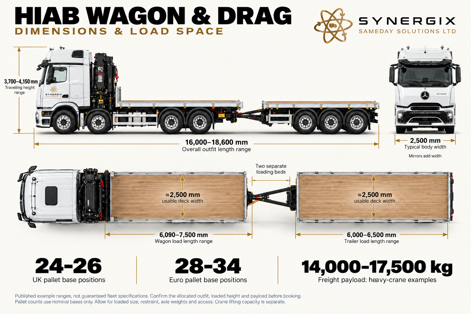
Front-crane HIAB wagon and drag: dimensions
Published planning examples. The actual vehicle, equipment, load distribution and access must be checked for your booking.
Open the full-size diagramDimensions and planning figures in text
Complete length 16,000–18,600 mm; travelling height 3,700–4,150 mm; body width 2,500 mm. Wagon deck 6,090–7,500 mm, trailer 6,000–6,500 mm, usable width about 2,500 mm. UK 24–26 / Euro 28–34 nominal bases. Heavy-crane freight examples 14,000–17,500 kg.
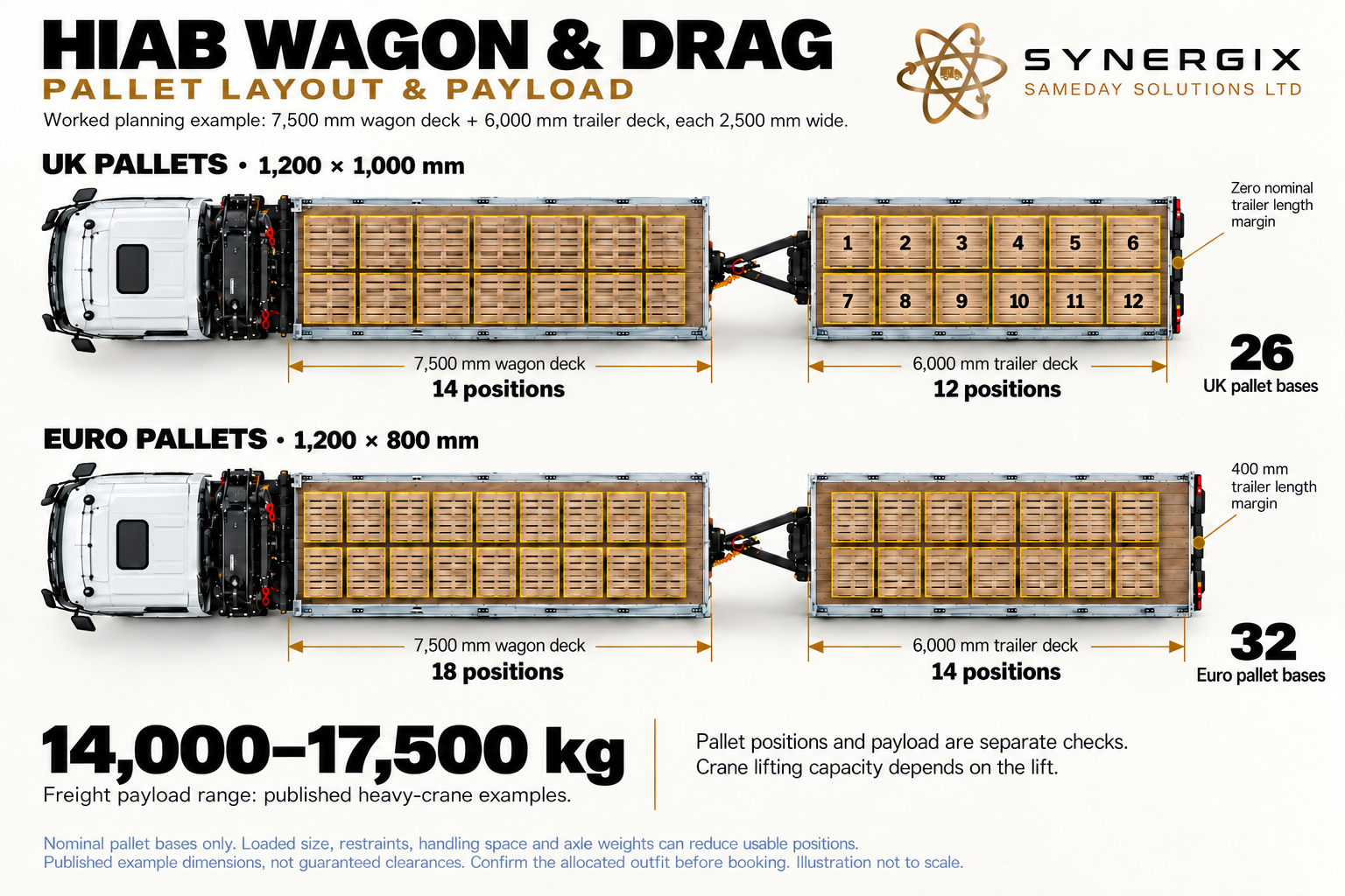
Front-crane HIAB wagon and drag: pallet layout
Published planning examples. The actual vehicle, equipment, load distribution and access must be checked for your booking.
Open the full-size diagramDimensions and planning figures in text
Worked floors 7,500 and 6,000 mm long × 2,500 mm. UK 14+12=26; Euro 18+14=32. UK trailer layout has zero nominal length margin.
A front crane, a rigid load deck and a drawbar trailer
Here the crane is behind the cab of the illustrated four-axle rigid, followed by its load deck and a separate drawbar trailer. The crane, truck body and trailer form a different working arrangement from the rear-crane version. The larger chassis installation and crane position need considering together, rather than treating the two wagon-and-drag pictures as equivalent.
The two platforms can carry suitable separate items in one movement, while the front crane serves the assessed collection and delivery positions. It can be useful for work needing both a particular crane installation and extra deck area, provided the loads divide appropriately and remain accessible to the handling plan.
The front position changes the radius to the trailer
With the slew centre near the cab, the crane may have to reach along or past the rigid body towards a load on the drawbar trailer. That distance includes the truck’s body layout and the coupling gap before reaching the trailer load. The crane may therefore need a different duty from a rear installation completing the same nominal lift.
A larger crane may make that arrangement useful, but its chart must cover the actual pick and place positions. Boom height, goods already on the rigid and where the trailer can stand all influence the operation. Moving the trailer or rigid to reduce a radius can introduce extra handling time and another support assessment.
What the four-axle rigid contributes
Additional axle capacity can help distribute the installed mass of a heavier crane, subframe, body and supports. That is part of making the complete heavy-crane vehicle viable on the road. The engineered frame and support system then carry the forces during the lift. The road axle layout and lifting support arrangement have related but distinct jobs.
The heavier installation can use much of the extra gross-weight allowance. It does not follow that this wagon carries a fixed amount more freight than the three-axle rear-crane arrangement. Compare the actual truck deck allowance, trailer allowance, combination limits and the crane’s rated duty, rather than assuming the trailer cancels the crane’s weight.
Two decks need their own loading plan
Allocate loads according to weight, dimensions, support points, axle distribution and unloading sequence. A single long rigid component belongs on a suitably long continuous platform, not across the truck and drawbar trailer. Multiple cabins or machines need enough room for restraint, rigging and the planned order of removal.
Where the trailer is left temporarily, agree a prepared location, support, braking, security and collection arrangement. If the truck will leave to make a separate delivery, describe that before booking. The body and crane must remain suitable in the resulting configuration, and the trailer needs to remain safely parked.
When to compare another arrangement
Compare rear-crane wagon and drag where working between the decks offers better pick distances. Compare a crane-equipped artic where one long flatbed platform suits the goods. Compare a smaller rigid where the load fits one deck and the whole drawbar combination would complicate access without adding useful capacity.
HIAB configuration 05 / 08
Three-axle HIAB tractor
Tractor unit / three axles
The crane-equipped tractor is shown without a trailer so its equipment arrangement is clear.
This is the tractor part of a combination, not a separate cargo deck. Agree the trailer, coupling, stability configuration and whether the planned operation requires it to remain coupled.
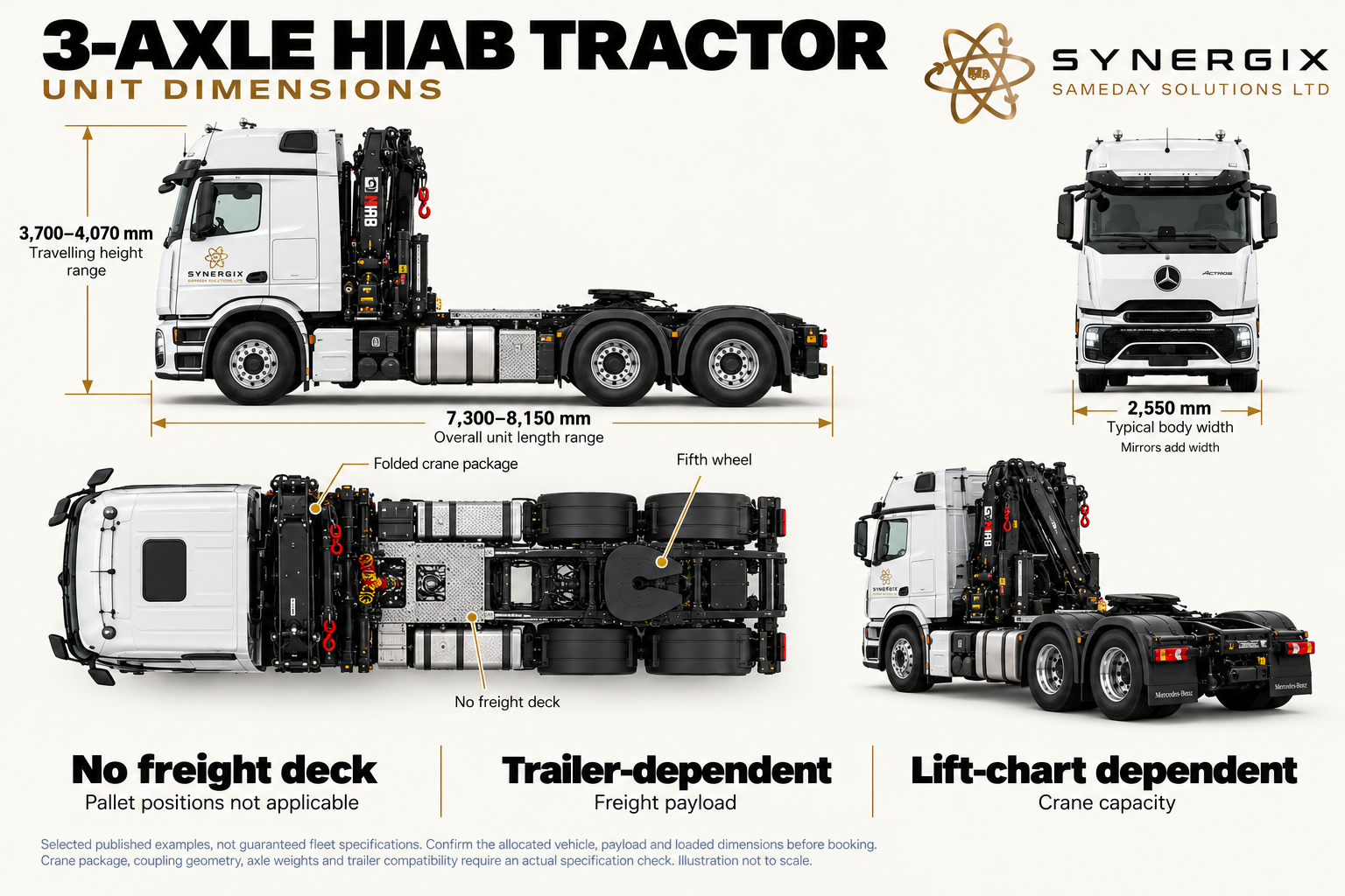
3-AXLE HIAB TRACTOR unit dimensions
Published planning examples. The actual vehicle, equipment, load distribution and access must be checked for your booking.
Open the full-size diagramDimensions and planning figures in text
overall Length: 7,300–8,150 mm, uncoupled; travelling Height: 3,700–4,070 mm, crane stowed; body Width: 2,550 mm; mirrors additional; load Length: Not applicable: uncoupled tractor; load Width: Not applicable: no freight deck; payload: Trailer-dependent. No pallet positions on the uncoupled unit. Companion sheet identifies the fifth wheel, crane package and air/electrical connections.
Coupling height and ratings, crane-to-trailer swing clearance, axle/train weights and lift chart require actual equipment data.
Published example sources:
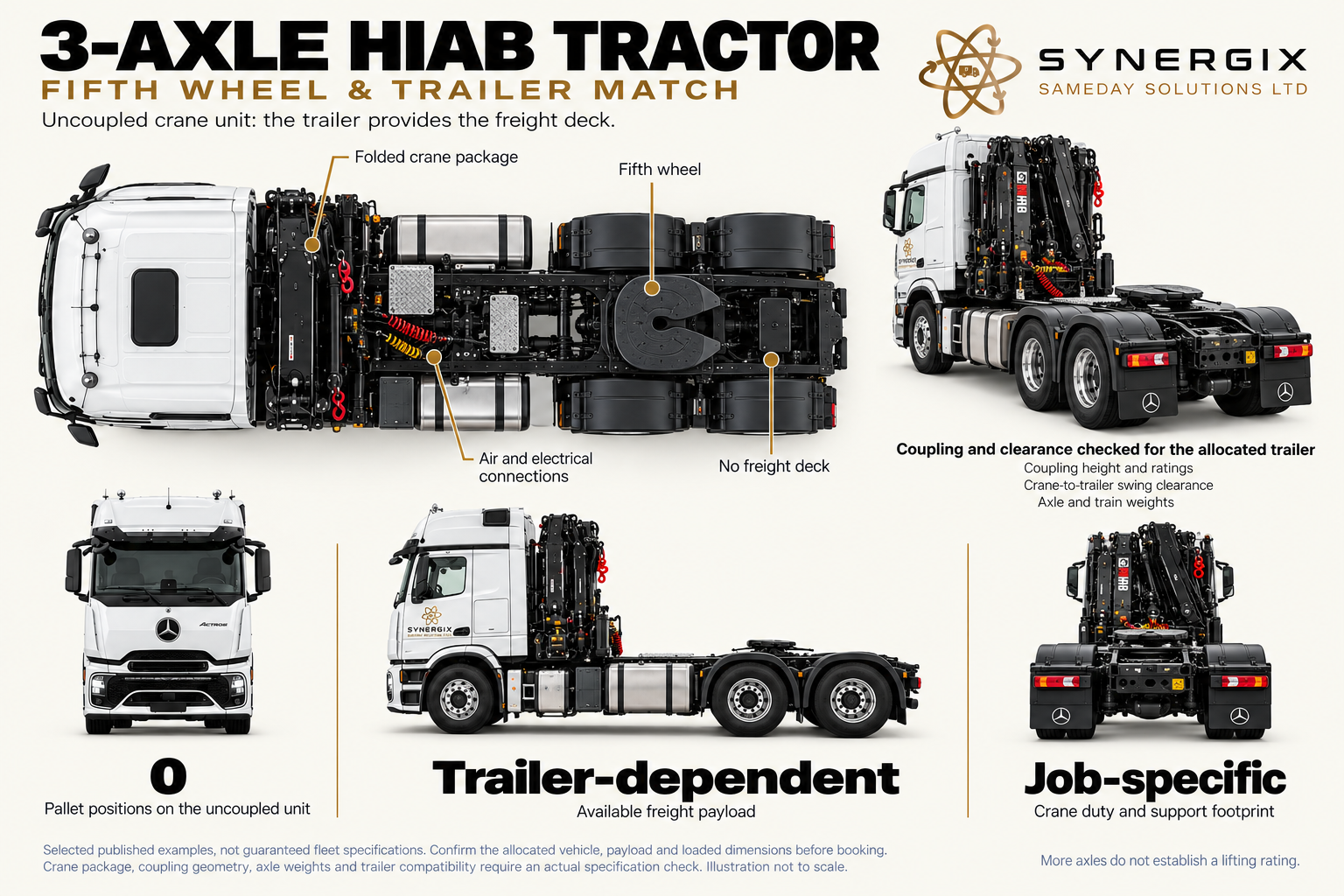
3-AXLE HIAB TRACTOR coupling layout
Published planning examples. The actual vehicle, equipment, load distribution and access must be checked for your booking.
Open the full-size diagramDimensions and planning figures in text
overall Length: 7,300–8,150 mm, uncoupled; travelling Height: 3,700–4,070 mm, crane stowed; body Width: 2,550 mm; mirrors additional; load Length: Not applicable: uncoupled tractor; load Width: Not applicable: no freight deck; payload: Trailer-dependent. No pallet positions on the uncoupled unit. Companion sheet identifies the fifth wheel, crane package and air/electrical connections.
Coupling height and ratings, crane-to-trailer swing clearance, axle/train weights and lift chart require actual equipment data.
Published example sources:
The crane tractor is a working unit, not an empty flatbed
The three-axle HIAB tractor combines the driving unit, mounted crane and equipment needed for the intended trailer combination. The picture shows it uncoupled so the crane installation and chassis arrangement are clear. Its role differs from a rigid flatbed: the normal freight platform is the selected semitrailer, not the space around the tractor’s fifth wheel.
This can provide flexibility where the job needs a crane-equipped tractor and a suitable separate load platform. It also helps explain why the complete combination must be specified. The tractor’s crane duty, trailer coupling and trailer layout have to work as one system for the goods being transported.
What the three axles have to carry
Before freight is added, the tractor carries its cab, engine, crane, subframe, hydraulic equipment, supports, fuel and driver. Coupling the semitrailer adds load through the kingpin. A crane behind the cab takes space and mass which an ordinary haulage tractor may not carry, changing the combination’s usable freight allowance and geometry.
Check fifth-wheel location and load, tractor axle distribution, trailer front clearance and the distance from the crane to the trailer’s load positions. The body builder’s design has to allow the combination to turn without the trailer colliding with the stowed crane, supports, equipment or cab. A trailer which couples mechanically is not necessarily a suitable crane-transport pairing.
Coupled and uncoupled lifting are separate questions
An approved installation can have configuration-specific stability arrangements. The presence, position or load state of a trailer can matter, so the uncoupled picture does not promise that every lift can be done with the trailer removed. We establish the actual operating configuration and chart for the job.
If the plan is to bring goods on another vehicle and use the crane tractor to lift them, describe that explicitly. Crane support, access for the carrying vehicle, lifting responsibilities and the complete timetable still need agreeing. This is a different brief from booking a single crane-and-flatbed delivery.
Three-axle versus four-axle crane tractor
A three-axle unit may offer a suitable balance of crane duty, road mass, coupling arrangement and manoeuvring for its installation. A four-axle heavy unit can support a different scale of crane and associated equipment. Compare the actual rated lifting requirement first, then the trailer and road freight, so a heavy installation is selected for useful capability rather than its appearance.
HIAB configuration 06 / 08
Four-axle heavy HIAB tractor
Heavy tractor / four axles
A four-axle tractor built around a substantial crane installation, illustrated with two front steering axles and a rear tandem.
Additional axle capacity helps distribute the installed crane and equipment mass alongside the trailer coupling load. Explore how crane rating, engineered subframe and supporting structure work together.
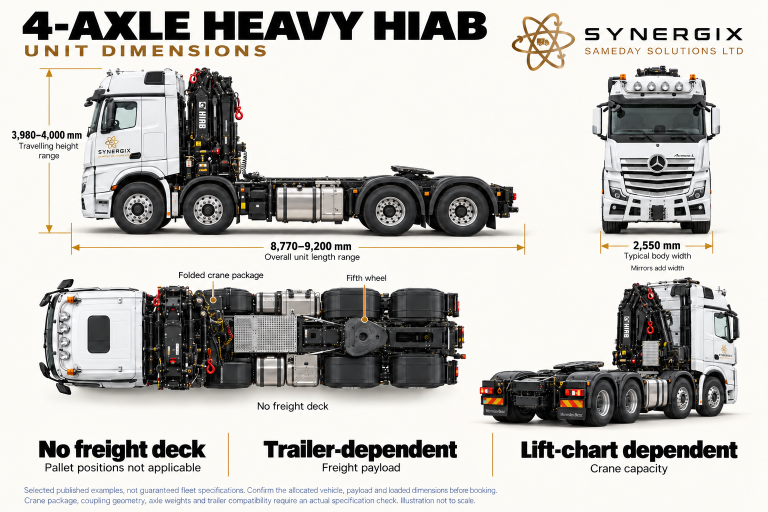
4-AXLE HEAVY HIAB unit dimensions
Published planning examples. The actual vehicle, equipment, load distribution and access must be checked for your booking.
Open the full-size diagramDimensions and planning figures in text
overall Length: 8,770–9,200 mm, uncoupled; travelling Height: 3,980–4,000 mm, crane stowed; body Width: 2,550 mm; mirrors additional; load Length: Not applicable: uncoupled tractor; load Width: Not applicable: no freight deck; payload: Trailer-dependent. No pallet positions on the uncoupled unit. Two front steering axles, equipment gap and rear drive tandem. Companion covers the fifth wheel and trailer compatibility.
No Synergix train-weight, towing or lift rating has been invented for the custom heavy-crane configuration.
Published example sources:
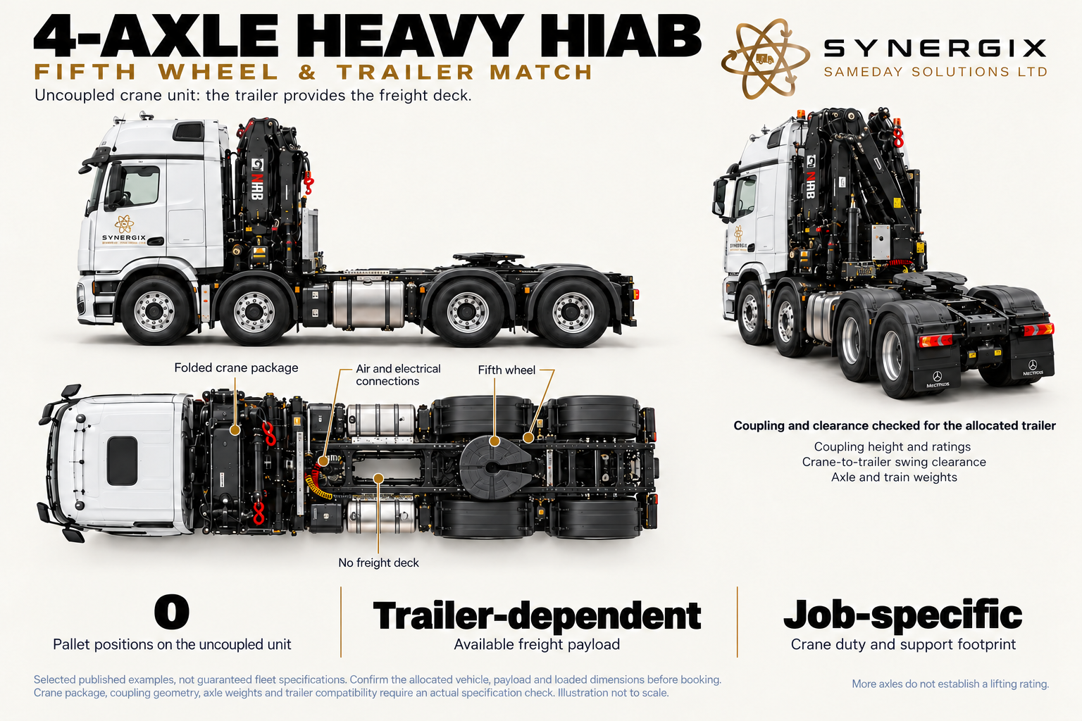
4-AXLE HEAVY HIAB coupling layout
Published planning examples. The actual vehicle, equipment, load distribution and access must be checked for your booking.
Open the full-size diagramDimensions and planning figures in text
overall Length: 8,770–9,200 mm, uncoupled; travelling Height: 3,980–4,000 mm, crane stowed; body Width: 2,550 mm; mirrors additional; load Length: Not applicable: uncoupled tractor; load Width: Not applicable: no freight deck; payload: Trailer-dependent. No pallet positions on the uncoupled unit. Two front steering axles, equipment gap and rear drive tandem. Companion covers the fifth wheel and trailer compatibility.
No Synergix train-weight, towing or lift rating has been invented for the custom heavy-crane configuration.
Published example sources:
A chassis built around a substantially heavier crane installation
The illustrated heavy tractor has four axles, with two front steering axles and a rear tandem. In this equipment class, the vehicle is selected around the crane’s mass and intended lifting duty, its engineered mounting, support system and trailer interface. The extra axle arrangement helps accommodate and distribute the weight of a large crane installation on the road.
This is directly relevant to crane capability. A large rated crane needs a carrier able to transport it and transmit its working forces through a suitable structure and support arrangement. Installed mass, axle distribution, mounting and supports are designed around the intended crane duty. Together, these make a particular heavy-crane installation possible.
Crane rating is the reason to examine the whole installation
A heavier crane can offer greater permissible loads at useful radii, a different boom/jib envelope or a more demanding placing duty, depending on its actual chart. That can make the heavy tractor valuable for a compact but heavy machine, or a load which is light enough to travel on an ordinary vehicle but must be placed much farther away.
The chassis does not create the crane’s structural rating. Rather, chassis, subframe, crane base, stabilisers and their control configuration must support the rated operation. A powerful crane fitted to an unsuitable carrier would not deliver the intended capability. Read the crane chart and the installation’s stability limits together.
Why the subframe and chassis support matter
The subframe is the engineered structure between the crane/body installation and the truck chassis. It helps distribute concentrated loads and transfer bending and torsional forces to the designed supporting points. Crane mounting and auxiliary stabiliser positions are part of that design. It is more than a deck reinforcement or a collection of extra bolts.
Manufacturer installation guidance distinguishes different frame designs, crane mounting positions, chassis properties and support layouts. Heavy installations may use additional supports towards the front or rear, but their presence and working sectors are specific to the built vehicle. Counting tyres or pads in a photograph cannot establish the permitted lifting zone.
The trade-off is lifting capability versus carried freight
A very substantial crane, long extensions or fly jib, winch, large subframe and additional support equipment all use vehicle mass. The tractor also has to accept the semitrailer’s kingpin load. Some heavy-crane work is therefore best organised with the crane vehicle and the freight-carrying vehicle planned separately, where the agreed arrangement allows it.
Even where a heavy tractor tows a large flatbed, do not assume a normal general-haulage payload. The complete ready-to-work mass, plates, axle distribution and route govern what can travel. The crane may have impressive close-in lifting capacity while the transport combination carries a comparatively modest consignment.
What to ask for when comparing a heavy-crane quote
Specify the heaviest complete lift, required horizontal radius, height, obstructions and landing point. Ask which crane/boom/jib configuration and working sector cover that duty, what carrier/support arrangement is proposed, how the goods will reach the crane and what site preparation is needed. Those answers are more useful than a headline tonne-metre class alone.
Compare the three-axle tractor if its actual crane chart covers the requirement. Compare a mobile crane plus separate haulage where the project is predominantly a demanding lift or the carrier cannot reach a suitable setup position. Neither alternative is automatically cheaper: mobilisation, transport, site space and lifting time determine the useful comparison.
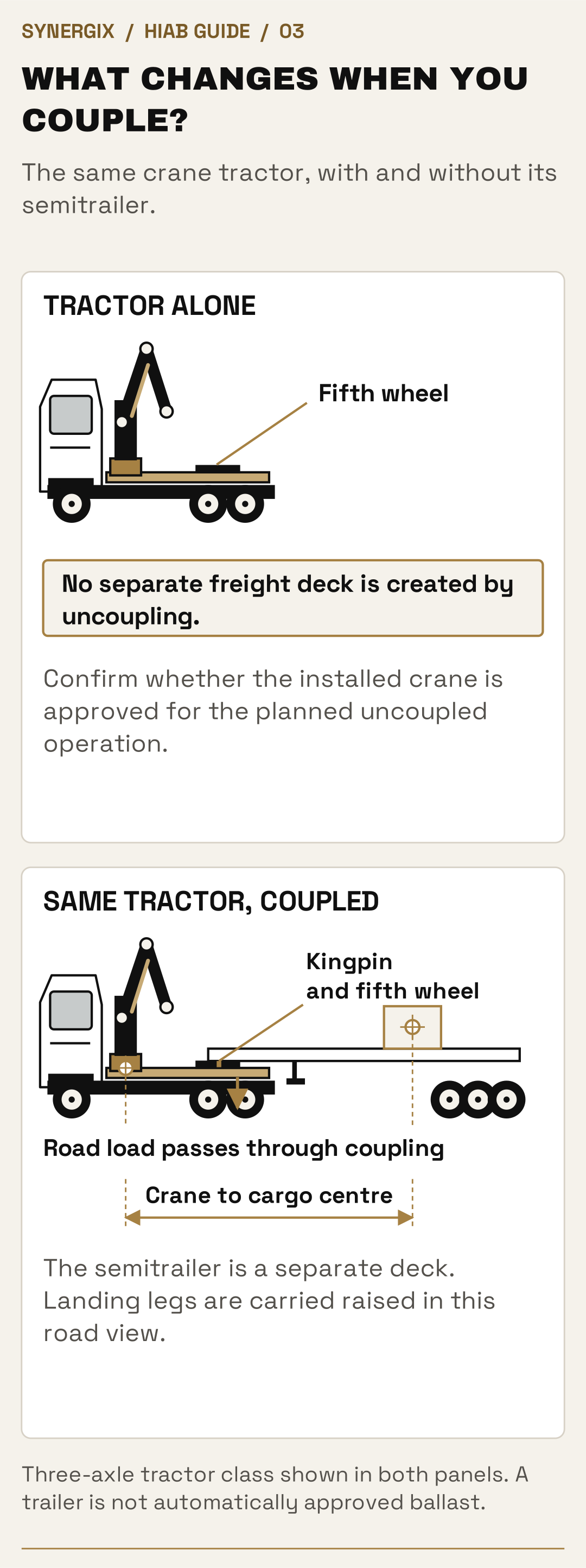
Three-axle tractor class shown in both panels. A trailer is not automatically approved ballast.
Open full-size desktop diagram · Open full-size mobile diagramHIAB configuration 07 / 08
HIAB artic & flatbed
Articulated / three-axle tractor
A three-axle crane tractor coupled to a flatbed semitrailer gives an open-deck articulated arrangement.
Consider the usable trailer deck, crane reach from the tractor, load position and the complete combination’s access. The trailer’s length is not the crane’s lifting radius.
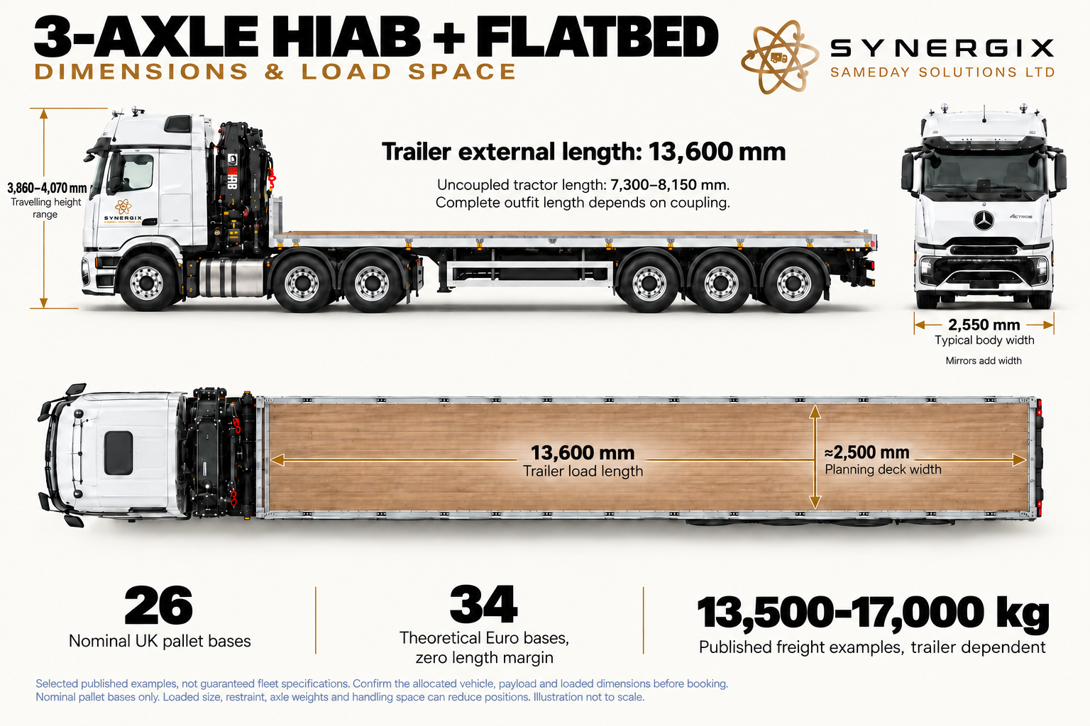
3-AXLE HIAB + FLATBED dimensions
Published planning examples. The actual vehicle, equipment, load distribution and access must be checked for your booking.
Open the full-size diagramDimensions and planning figures in text
Trailer external and load length 13,600 mm, per Henry. Uncoupled tractor 7,300–8,150 mm; body 2,550 mm wide; stowed height 3,860–4,070 mm. Worked deck 13,600 × 2,500 mm: 26 UK or 34 theoretical Euro. Published freight examples 13,500–17,000 kg.
Complete outfit length depends on coupling. Tractor and trailer lengths must not be added. 34 Euro is a theoretical zero-length-margin layout, not guaranteed bookable capacity.
Published example sources:
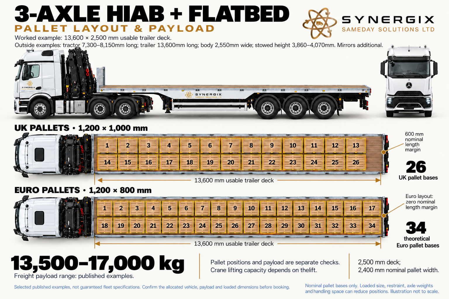
3-AXLE HIAB + FLATBED pallet layout
Published planning examples. The actual vehicle, equipment, load distribution and access must be checked for your booking.
Open the full-size diagramDimensions and planning figures in text
Trailer external and load length 13,600 mm, per Henry. Uncoupled tractor 7,300–8,150 mm; body 2,550 mm wide; stowed height 3,860–4,070 mm. Worked deck 13,600 × 2,500 mm: 26 UK or 34 theoretical Euro. Published freight examples 13,500–17,000 kg.
Complete outfit length depends on coupling. Tractor and trailer lengths must not be added. 34 Euro is a theoretical zero-length-margin layout, not guaranteed bookable capacity.
Published example sources:
The crane tractor with its freight platform attached
The three-axle HIAB tractor and flatbed semitrailer provide a crane-equipped articulated transport arrangement. Compared with the tractor-only view, the trailer supplies the continuous cargo platform. Compared with wagon and drag, there is one trailer deck rather than two separate truck-and-trailer decks.
This arrangement is worth considering for longer supported items, several loads needing one continuous platform, or freight whose length/layout does not suit a rigid. A flatbed also provides open side and overhead access for agreed loading. Whether it is the right answer depends on both the road load and the crane duty at the collection and delivery points.
Deck length does not describe crane reach
The crane is near the tractor, so a load towards the far end of the semitrailer can be substantially farther from the slew centre than a load near its front. A long deck gives carrying space; it does not guarantee that every position is reachable at the same mass. Rear loads, tall freight and equipment in the way can change the lifting geometry.
The loading plan considers where items sit, how the crane can attach to them and what must be lifted first. In some jobs the site provides separate loading equipment at one end; in others both ends require the onboard crane. Tell us which arrangement applies. A crane useful at delivery does not eliminate the need to plan collection.
Kingpin load, crane weight and the trailer
The semitrailer shares its load between its axles and the tractor through the kingpin. A heavy item near the front can add significantly to the tractor’s already substantial crane installation. Moving it rearward can increase trailer-group load and may increase the crane’s pick radius. Freight position is therefore both a road-distribution and a handling decision.
Floor strength, concentrated bearing loads and suitable dunnage matter for machinery, steel and cabins. A long machine supported on a few small feet can be a more demanding deck load than distributed pallets of the same total mass. The lifting points, support points and road restraint points are not automatically interchangeable.
Access and unloading need the whole artic
Allow for the tractor, trailer, turning path, tail swing, stabilisers and the landing area. A gate wide enough for a rigid crane lorry may still be unsuitable for the articulated combination. If a trailer must be uncoupled or moved during the work, its support and the crane’s approved operating configuration need including in the plan.
Compare a rigid HIAB where the goods fit a single shorter deck and site access is the deciding factor. Compare the four-axle heavy artic where the required lifting duty justifies that installation. Compare plain articulated haulage with site lifting when the receiving facility already has suitable equipment.
HIAB configuration 08 / 08
Heavy HIAB artic & flatbed
Heavy articulated / four-axle tractor
The heavy four-axle crane tractor is coupled to a flatbed semitrailer, bringing a substantial lifting installation and a continuous freight platform together.
Compare the rated lifting duty with the carrying platform, installed mass, kingpin distribution and site plan. This arrangement can earn its place through a demanding lift even when the goods do not fill the deck.
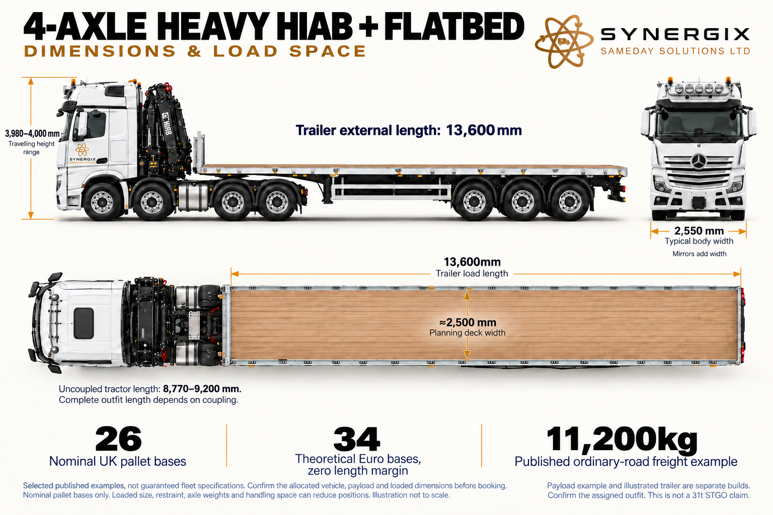
4-AXLE HEAVY HIAB + FLATBED dimensions
Published planning examples. The actual vehicle, equipment, load distribution and access must be checked for your booking.
Open the full-size diagramDimensions and planning figures in text
Trailer external and load length 13,600 mm, per Henry. Uncoupled tractor 8,770–9,200 mm; body 2,550 mm wide; stowed height 3,980–4,000 mm. Worked 13,600 × 2,500 mm deck: 26 UK or 34 theoretical Euro. Published ordinary-road freight example 11,200 kg.
Payload and trailer illustration are separate builds. Full physical outfit length depends on coupling. 34 Euro has zero nominal length margin.
Published example sources:
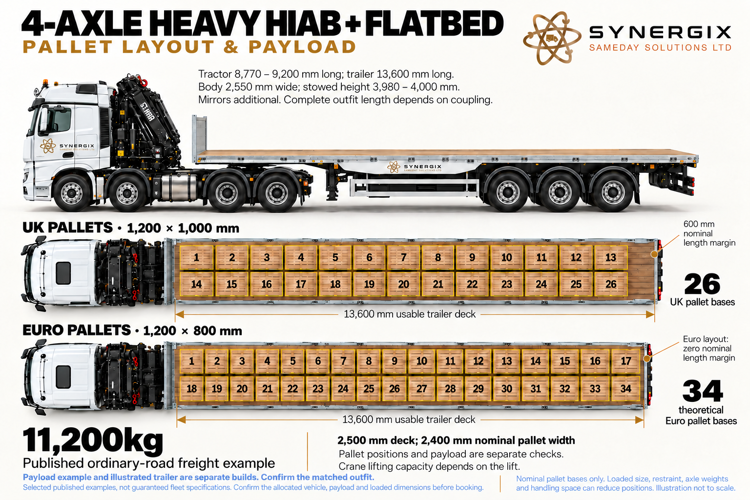
4-AXLE HEAVY HIAB + FLATBED pallet layout
Published planning examples. The actual vehicle, equipment, load distribution and access must be checked for your booking.
Open the full-size diagramDimensions and planning figures in text
Trailer external and load length 13,600 mm, per Henry. Uncoupled tractor 8,770–9,200 mm; body 2,550 mm wide; stowed height 3,980–4,000 mm. Worked 13,600 × 2,500 mm deck: 26 UK or 34 theoretical Euro. Published ordinary-road freight example 11,200 kg.
Payload and trailer illustration are separate builds. Full physical outfit length depends on coupling. 34 Euro has zero nominal length margin.
Published example sources:
Heavy lifting equipment and a separate flatbed deck
This couples the four-axle heavy crane tractor to a flatbed semitrailer. The combination brings a substantial crane installation together with a separate transport platform. Its value is the ability to plan particular heavy or extended-reach lifting duties alongside suitable freight movement, rather than treating crane hire and haulage as unrelated last-minute bookings.
It can be considered for appropriate heavy machinery, large supported structures, containers or modular equipment when the actual crane, trailer and route suit. A load does not have to fill the deck to justify this equipment. One compact item at a demanding placing radius can be the reason for the heavy crane.
The tractor remains the heavy-crane installation
The crane’s own mass, engineered subframe, support layout, hydraulic equipment and any jib/winch remain on the tractor. The trailer adds a cargo platform and further road mass; it does not remove those demands. Its coupling load must remain compatible with the tractor’s axle and fifth-wheel limits.
Four tractor axles plus the trailer’s axles do not create an automatic entitlement to a particular gross combination weight. Ordinary legal limits, the actual plates and, where applicable, the correct abnormal-load arrangements have to be established. More axles and a heavy-looking trailer are not a substitute for that assessment.
Road payload and crane capacity can point in different directions
A larger crane may solve the lift while reducing the freight that the combination can carry. A longer or heavier-duty trailer may solve support and deck-space needs while adding more tare. A useful quotation therefore identifies the whole vehicle, the carrying allowance and the rated crane duty, not just a trailer length and a maximum lifting headline.
For some projects, one vehicle brings the freight and another provides the heavy lift. That can place the crane closer to the landing point or allow the goods to travel on a better-suited carrier. The comparison must include the extra vehicle, setup space, traffic management, operator/rigging resources and the interfaces between them.
Long or heavy freight still needs a load plan
Position individual items for deck strength, axle and kingpin distribution, restraint, reach and unloading order. A heavy item cannot be moved to an arbitrary point just to improve crane radius. Any intermediate repositioning requires a suitable planned method and time; it is not an assumed service performed on arrival.
At the receiving site, establish a viable support area for the heavy tractor and clear space for the semitrailer or separate carrier. Draw the whole operation, including roof lines, projections, excavation edges and where the goods must finish. The support and swept areas can be the deciding factor even when the road approach is suitable.
When the heavy combination earns its place
Select it because the actual load chart and installation meet a duty that a smaller arrangement does not, or because the combined deck and handling plan provides a better complete movement. If a smaller rigid can carry and place the goods appropriately, it may avoid unnecessary mobilisation and site space. We compare those options against your actual requirement.
Two separate platforms
Plan the wagon.
Plan the trailer.
Both decks and their handling belong in the brief
The two wagon-and-drag variants above have different crane positions and chassis arrangements. This existing conceptual drawing explains the separate platforms and overall manoeuvring requirement. It is not a front-versus-rear crane comparison or a swept-path calculation.
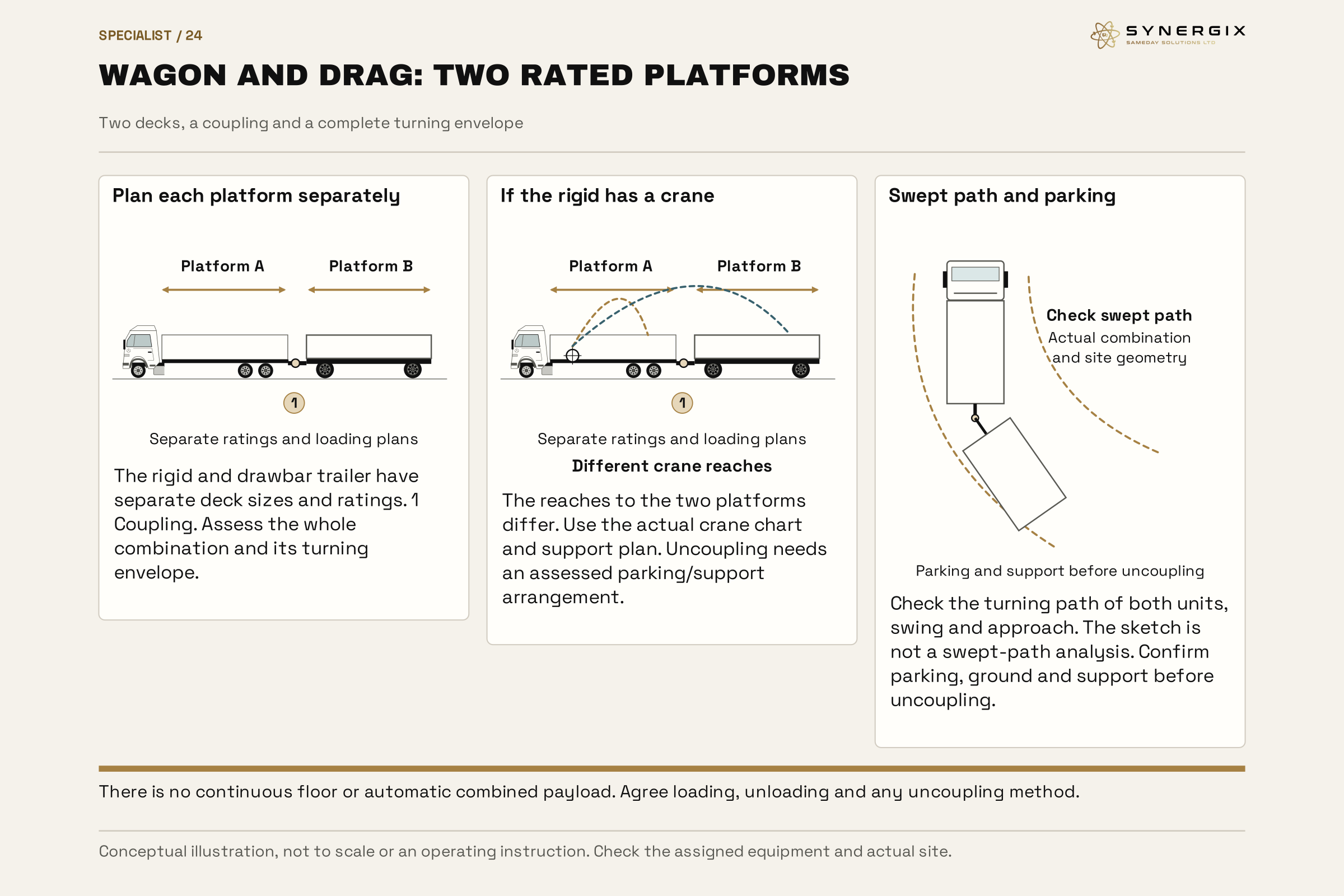
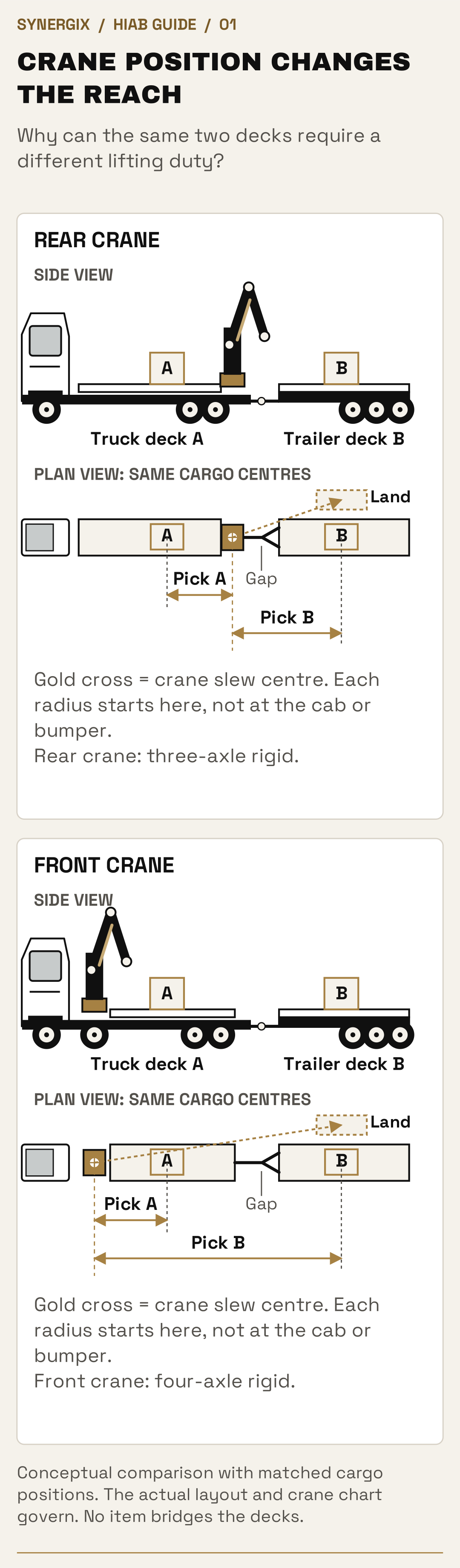
Conceptual comparison with matched cargo positions. The actual layout and crane chart govern. No item bridges the decks.
Open full-size desktop diagram · Open full-size mobile diagramCrane capacity and working envelope
The reach changes
what the crane can lift.
A HIAB is a vehicle-mounted loader crane, usually with a folding knuckle boom. HIAB is a brand name; customers also use the term for lorry-loader crane transport. Unlike a MOFFETT forklift, the crane lifts from its mounted position rather than driving the goods across the site.
Payload is what travels.
The road vehicle must carry the goods, crane, supports, fuel and other equipment within its actual gross and axle limits. A crane installation uses some of the allowance that a standard body could otherwise make available to freight.
Lift capacity is what the crane can handle.
The permissible suspended load depends on the actual crane chart at the required radius, boom/jib arrangement, fitted lifting gear and stability configuration. Being within the vehicle payload does not approve the lift.
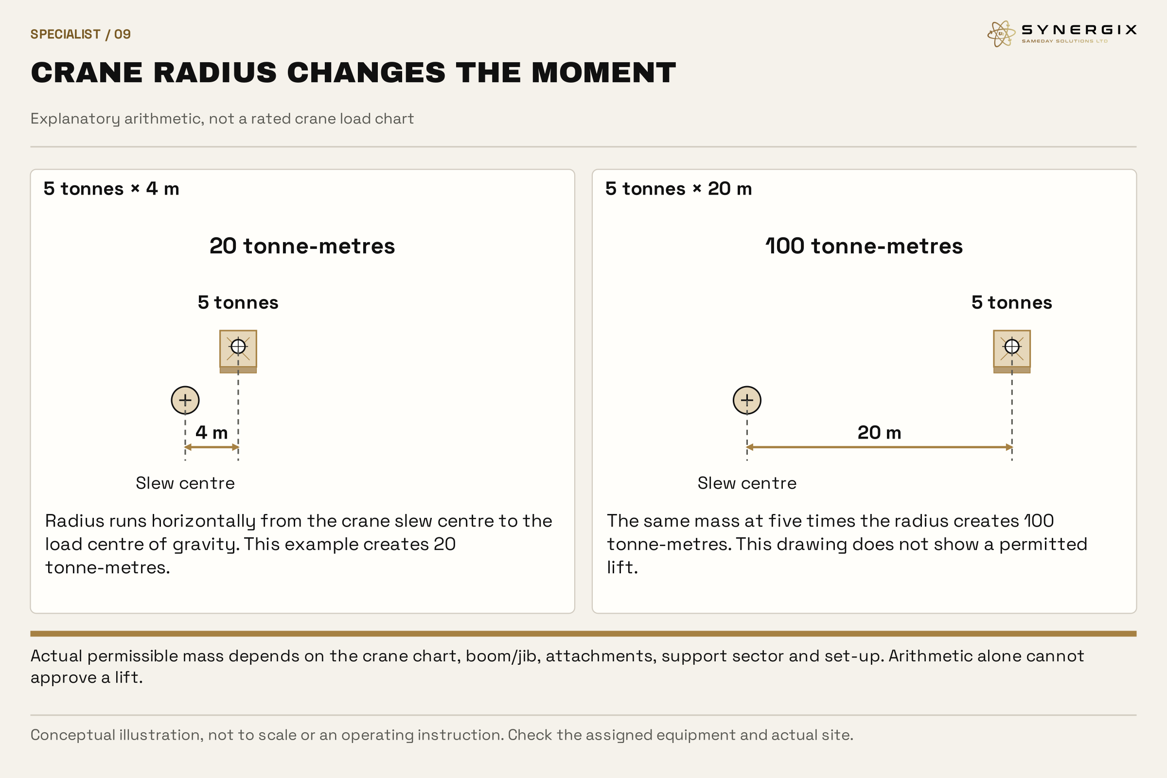
Five tonnes close in is a different job from five tonnes at 20 metres.
Working radius is the horizontal distance from the crane’s slew centre to the load’s centre of gravity. As an explanation of lifting moment, 5 tonnes × 4 metres = 20 tonne-metres; 5 tonnes × 20 metres = 100 tonne-metres. These figures explain the effect of distance. They do not establish a safe crane capacity.
The actual chart governs the job. Include the mass of lifting accessories and account for any attachments. A jib or extra extension changes the configuration; a model number, maximum outreach or headline tonne-metre rating alone cannot approve the load at the placing point.

Crane position changes the plan.
A behind-cab crane, rear-mounted crane and tractor-mounted crane begin at different positions relative to the cargo and landing point. Front and rear arrangements therefore need different radius and loading checks.
The working sector matters.
Permissible lifting can vary around the vehicle and with the support configuration. Reduced stabiliser extension is only considered where the equipment and the assessed plan allow it. Electronic monitoring does not create space or strengthen weak ground.
Crane class, tonnes and tonne-metres are different descriptions
A tonne is a mass. A tonne-metre describes mass multiplied by horizontal radius and is used to express a lifting moment or class. A “90 tonne-metre class” crane is not a promise to lift 90 tonnes, nor a guarantee of any particular load at maximum outreach. Model names and marketing classes are starting points for finding the right specification.
The usable capacity is obtained from the chart for the relevant crane, boom/jib, height/radius and installed stability arrangement. The weight of the boom and fitted equipment matters, so dividing a headline moment by the radius does not create a valid substitute chart. Close-in lifting, maximum horizontal reach and maximum vertical reach are different parts of the envelope.
| Published item | Manufacturer information | What it teaches |
|---|---|---|
| Range description | 90 Tm lifting class; horizontal reach up to 34.4 m and vertical reach up to 38.5 m across the advertised configurations. | Different headline maxima are not one simultaneous lifting duty. |
| Named E-10 model row | 23.9 m hydraulic extension outreach, 742.5 kNm lifting-capacity entry and 9,189 kg weight. | The exact model row gives a different, configuration-specific description from the range headline. |
| Status of this example | Manufacturer’s published product information, reviewed 23 October 2026. | It is not confirmation that Synergix supplies this model, its jib options or any of these ratings. |
Read the complete required duty
Establish the pick radius and height, the load’s route through the working envelope and the final radius and height. A load can be acceptable at the start and beyond the permissible duty at the destination. Lifting over an obstruction can require height and geometry which a simple plan-view distance misses.
The chart and operating instructions establish how lifting gear and attachments are counted. A 4,000 kg machine with 200 kg of relevant suspended rigging creates a 4,200 kg suspended demand before any other allowance required by that chart. This is arithmetic only, not a selected crane or approved lift.
What to supply if you cannot measure the final radius
Send a marked plan or photographs showing the goods, possible vehicle position, landing point and intervening structures. Include roof and wall heights, overhangs and the final support/base. The operator/planner can then establish the working geometry with the proposed equipment. Guessing from a postcode or the length of the truck cannot do this.
If conditions change, such as a parked vehicle blocking the agreed setup point, the same load may now require a longer radius or a different working sector. Report the change before the movement. A chart checked for the original location does not settle the revised operation.
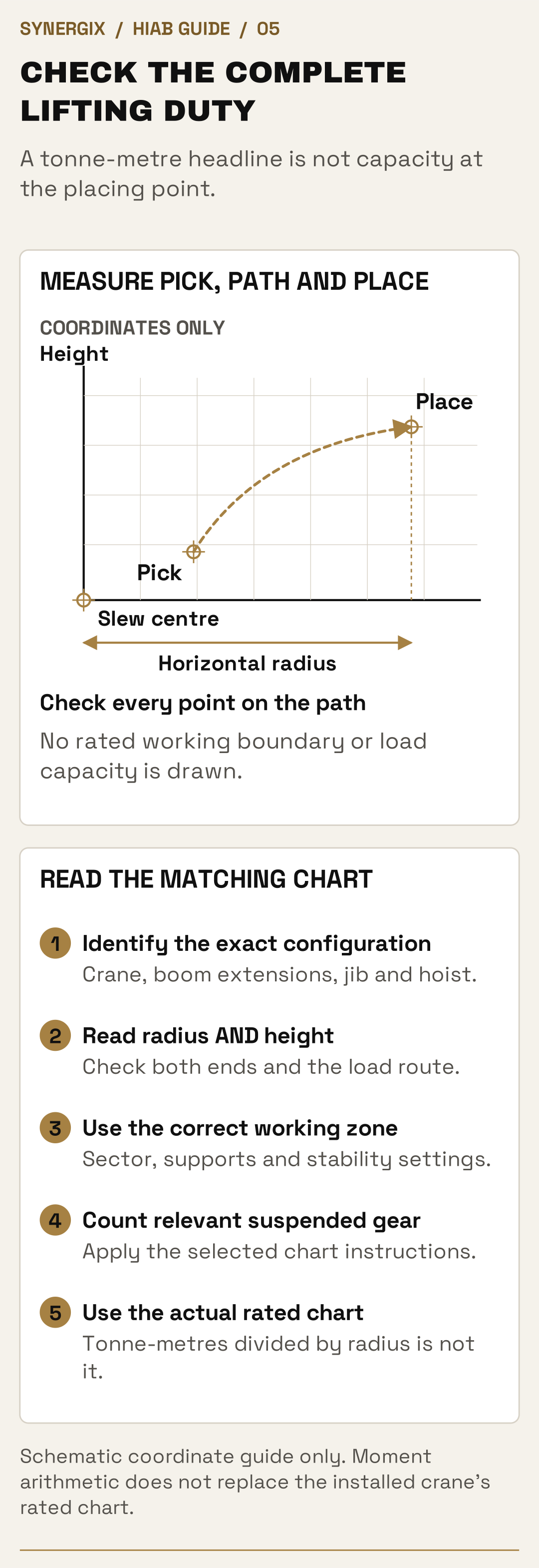
Schematic coordinate guide only. Moment arithmetic does not replace the installed crane’s rated chart.
Open full-size desktop diagram · Open full-size mobile diagramChassis, subframe and stability
How the vehicle
supports the crane.
From the hook to the supporting ground
A suspended load applies forces and an overturning effect through the boom to the crane column and base. The crane installation transfers those effects into its supporting structure and stabilisers, then into the supporting surface. Road-going chassis, mounting system and support layout therefore form part of the lifting installation, alongside the crane itself.
During road travel, axles and tyres support the moving vehicle within its limits. During lifting, the manufacturer’s specified support setup applies. Extra road axles do not replace deployed stabilisers, and a stabiliser layout does not remove the need for lawful axle loads on the journey. Instructions about wheel contact or suspension are installation-specific; customers should not assume every crane truck uses the same setup.
What an engineered subframe contributes
A subframe connects the crane/body installation with the base chassis and distributes working forces through the designed structure. The design has to address bending, twisting, the crane’s position, available space and any auxiliary supports. Different designs are used for different applications, including rear cranes and tractor combinations.
A heavy crane can need a substantial structure as well as the lifting machine itself. Hiab’s published FrameWorks 858/1058 example lists a 3,616 kg medium-built frame before the separately listed attachment kits. This historical manufacturer example illustrates why the installation has material mass; it is not the frame weight of our pictured vehicles or a universal deduction from payload.
Why four axles can be part of enabling the heavy crane
The heavy crane and its supporting equipment have to be carried in acceptable positions on a suitable chassis. Additional axle capacity can help distribute that installed mass and, on a tractor, the load accepted from the semitrailer. The vehicle’s wheelbase, axle arrangement, steering layout, frame and coupling installation affect the achievable combination.
That is why a four-axle heavy-crane unit can be a materially different lifting solution from an ordinary three-axle crane tractor. It can carry and support a different installation. The resulting rated duty still comes from the actual crane chart, structure and stability configuration, not a fixed conversion from axle count to tonnes lifted.
Stability systems work with the installation
Some cranes monitor support extension, working sector and other installation inputs to determine permitted operation. Manufacturer systems can provide different lifting envelopes for different support positions. This can make an assessed restricted-space operation possible on appropriately equipped installations, but it does not justify simply leaving legs partly retracted on another machine.
Trailer contribution is also configuration-specific. Palfinger’s installation guidance describes an optional system that can account for semitrailer kingpin load after configuration and adjustment. That is an example of engineered integration, not permission to treat any trailer or carried freight as ballast. Uncoupling or unloading can change the approved situation.
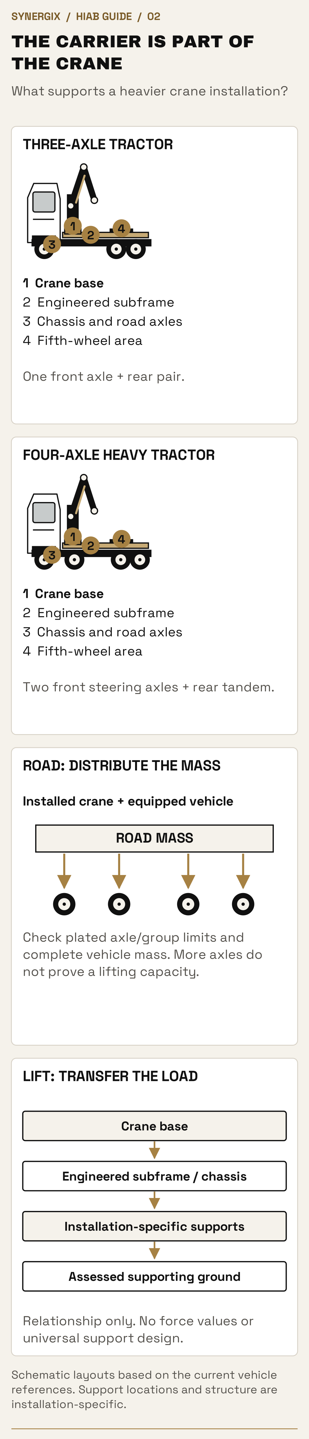
Schematic layouts based on the current vehicle references. Support locations and structure are installation-specific.
Open full-size desktop diagram · Open full-size mobile diagramBoom equipment and load attachment
Jibs, winches
and lifting points.
Knuckle boom, telescopic sections and fly jib
A loader crane’s articulated boom folds for transport and changes geometry to reach its working position. Telescopic sections extend the boom. A fly jib is an additional articulated extension which can add reach and positioning options. It brings its own mass, movement and chart requirements; it is not free extra capacity.
A jib can be useful where an obstacle or placing geometry requires a different boom arrangement. It may also require more overhead space to unfold and more setup time. State the load height and required destination, rather than asking for a particular attachment without the working brief.
Fixed hook and winch are different handling arrangements
A fixed-hook lift changes position through crane movement. A compatible winch/hoist uses wire rope and associated equipment to raise or lower the hook, offering another way to control vertical movement. The crane/jib, hoist, rope arrangement and fitted components each have relevant limits. Adding a winch does not increase every crane duty.
Describe any below-ground or unusually high placing requirement, limited headroom or need for precise vertical lowering. Those details may change the equipment, rigging and supervision needed. A website illustration is not a rope-reeving or operating instruction.
Lifting points, centre of gravity and sling geometry
The load’s centre of gravity may not be at the middle of its outline. Motors, tanks, contents and installed equipment can make one side heavier. Suitable identified lifting points, their ratings and the manufacturer’s lifting information help determine a stable lifting arrangement. A forklift pocket, road tie-down eye and lifting lug are not automatically interchangeable.
Slings, chains, shackles and lifting beams must suit the load, their connection, the lifting method and the relevant angles. A wider sling angle can increase leg forces. Sharp edges, crushable packaging, painted surfaces and fragile structures may need an alternative support or protection arrangement. Do not assume each leg takes an equal share.
Why a spreader or lifting beam can matter
A suitable lifting beam or spreader arrangement can help achieve the required support geometry or avoid harmful inward forces on particular loads. It also adds suspended mass and consumes headroom. The crane still needs to reach above the load with space for the complete rigging assembly, not merely clear the top of the goods.
For a cabin or container, identify whether the approved method uses designated corner fittings, lifting points or another engineered arrangement. Contents must be included and suitably secured. The correct hardware and method are decided from the actual unit, not from the fact that it looks like a standard shipping container.
Who connects and directs the load?
Agree the people needed to attach the load, direct its movement and supervise the operation. Some routine work can combine roles where competence and circumstances allow; more complex work can need additional people. Remote control can help an operator choose a useful viewpoint, but it does not remove the need for signalling, segregation or visibility of the complete task.
Tell us if the operator will lose sight of the load behind a building, if work is inside an occupied site or if more than one lifting machine is proposed. Blind, tandem and non-routine lifts need their own planning. They must not be improvised from an ordinary delivery booking.
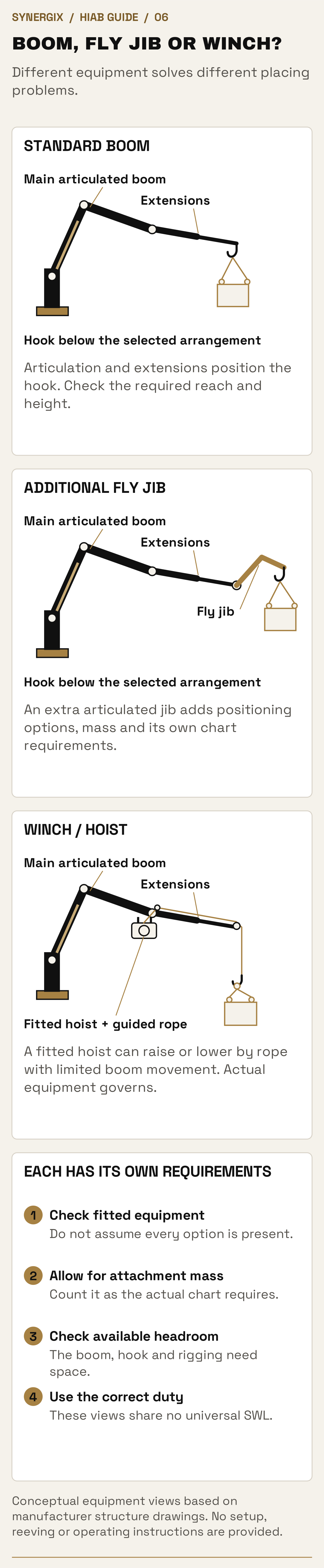
Conceptual equipment views based on manufacturer structure drawings. No setup, reeving or operating instructions are provided.
Open full-size desktop diagram · Open full-size mobile diagram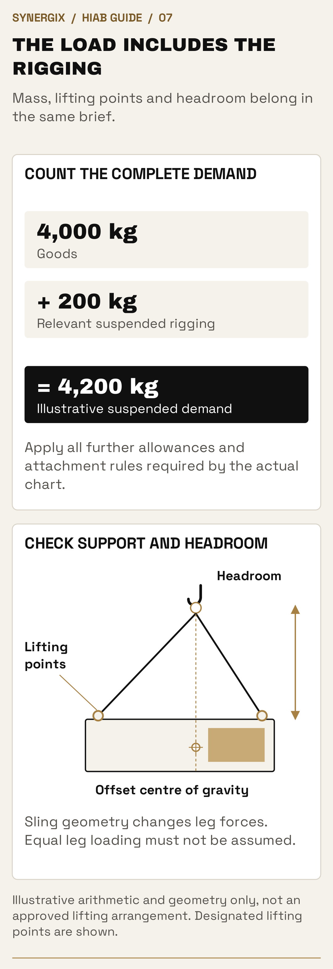
Illustrative arithmetic and geometry only, not an approved lifting arrangement. Designated lifting points are shown.
Open full-size desktop diagram · Open full-size mobile diagramRoad access and the working area
Space for the lorry.
Space for the lift.
Getting the vehicle there
Send entrance widths, approach restrictions, turning/reversing space, overhead clearance and any vehicle weight limits. Include the trailer on articulated and wagon-and-drag jobs. An access exemption does not override a separate bridge restriction or physical obstruction.
Supporting the crane
Flag soft ground, recently laid surfaces, slopes, verges, basements, culverts, drains, buried services and excavation edges. Stabilisers concentrate load. Pads and support need selecting for the assessed ground and forces, not just the space available.
Room to work
Allow for the required stabilisers, boom movement, load path and exclusion area. Check the complete vehicle position and the final placing point. A rear-mounted crane does not automatically reach anywhere on both wagon-and-drag decks.
Overhead lines and obstructions
Identify power lines, roofs, trees and other overhead hazards before booking. Clearance is not judged by eye. Power lines require a properly assessed arrangement with the relevant parties; this guide supplies no universal safe distance.
Photograph the whole operation. Send the entrance and approach, the parking/support area, the goods and the landing position. Include anything between them. A clear view of the destination alone can miss the obstruction that prevents the vehicle from setting up.
Wind and the load’s exposed area can change the lifting decision. A large light panel may present a different problem from a compact heavy machine. If conditions or the agreed site arrangement change, the lift needs reassessing before work continues.
Ground bearing is about concentrated support loads
The weight of the suspended load is not divided equally between all visible legs. Crane position, radius, working sector, vehicle and boom mass can concentrate a substantial reaction at one support. The planner needs the relevant support reactions and reliable information about the ground, not just the total cargo weight.
Pads or mats spread load over a larger area, but they also have to carry and distribute it without bending or punching through. A larger pad does not turn an unknown surface into known competent ground. Paving above a cellar, recently backfilled ground, a drain cover or an excavation edge can look sound while lacking the required support.
Parked size, deployed size and the load path
Measure the approach and the working area separately. The lorry has to enter, turn and park, then deploy the required support system. The boom needs room to unfold and slew, with clearance for the load, rigging and people working outside the exclusion area. A setup point may be usable for arrival but unsuitable for the proposed lift.
The destination needs preparation too: a supported base or bearers, correct orientation, access to remove lifting gear and enough room for the crane to disengage. Container doors, control panels and maintenance access can end up on the wrong side if the final orientation is not agreed. Think about later collection or removal as well as the first delivery.
Wind, exposed area and lifting above obstacles
A large panel, empty cabin or broad load can catch wind even when its mass is modest. Gusts and local turbulence around structures can affect control. Manufacturer limits, the load’s exposed area and the actual conditions inform the decision; one wind-speed number is not a universal go/no-go rule for every crane and load.
Lifting above a wall or roof adds height and clearance demands. The required boom arrangement may change as the load moves. Describe the obstruction’s location and dimensions, rather than giving only the horizontal distance to the landing point. Work near overhead power lines requires an assessed arrangement with the appropriate parties, not a guessed clearance.
Roadside work, pedestrians and changing sites
If setup occupies a public road, footway or shared traffic area, permissions and traffic/pedestrian arrangements may be needed. The site must identify who prepares and controls the area. School entrances, occupied workplaces, event build traffic and passing vehicles can change what resources and timing are appropriate.
Tell us about gate times, induction, security, permits, temporary ground protection, nearby lifting equipment and any change since the photographs were taken. A site survey can resolve unclear access or support information. It is useful preparation where needed, rather than a substitute for supplying the basic load and site details.
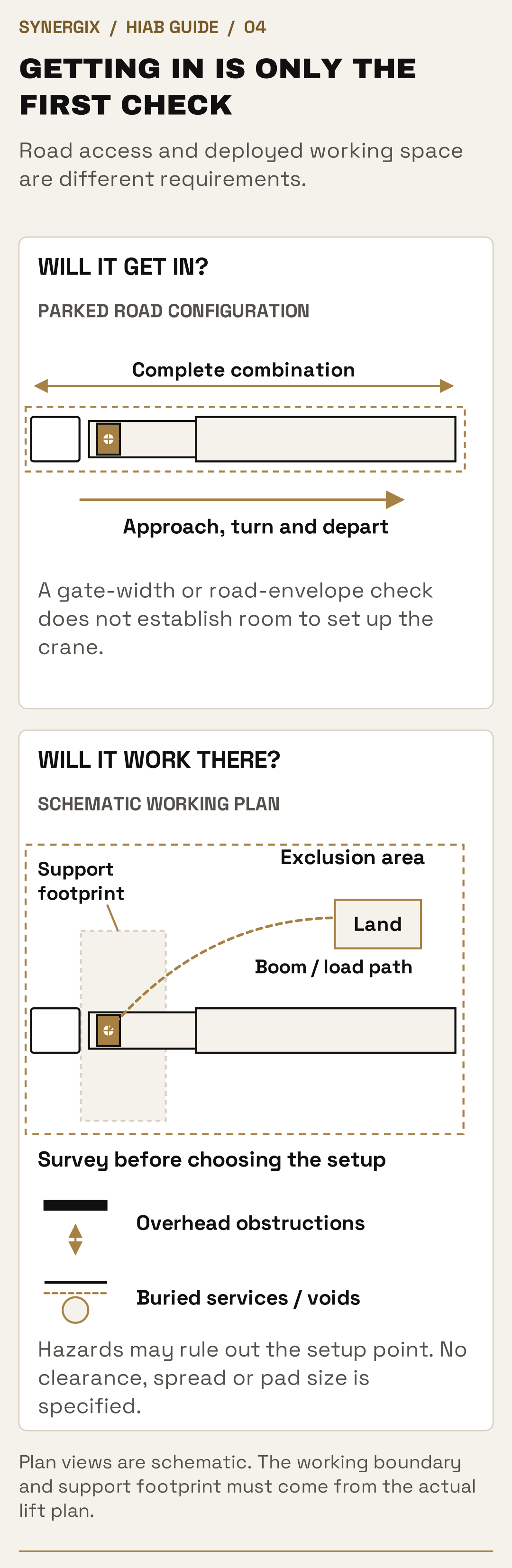
Plan views are schematic. The working boundary and support footprint must come from the actual lift plan.
Open full-size desktop diagram · Open full-size mobile diagramLoads and applications
Choose around
what needs moving.
Containers and cabins
Provide the empty or loaded weight, contents, dimensions and suitable lifting points. Confirm the prepared base and the required door orientation. Container corner fittings do not automatically make every lift acceptable.
Machinery and plant
Send the machine’s transport weight and drawings where available. Highlight offset centres of gravity, loose parts, fluid contents and restricted lifting points. Supports and restraint need to suit the load during the journey too.
Building and industrial materials
Long packs, steel, frames, pipes and bulk bags need appropriate support and lifting arrangements. Packaging must withstand the agreed method; a pallet suitable for forks is not automatically suitable for slings.
Events and festivals
HIAB lifting can support suitable event structures and equipment where the vehicle can set up safely. Tell us about event build/breakdown windows, ground conditions, public segregation and access that changes during the event.
Awkward or high-value equipment
Explain fragility, approved support points and any limits on tilting or rotation. We agree the handling scope, placing point and applicable cover for the goods rather than treating every lift as routine.
Repeat and multi-site movements
Provide each collection/delivery arrangement. A load and crane suitable at one site may need a different set-up at the next, particularly after part of the freight has been unloaded.
A lift to an agreed placing point is different from installation, positioning inside a building or commissioning equipment. Tell us the complete requirement so the transport and any further handling can be agreed together.
Cabins, containers and portable buildings
Send the exact unit type, dimensions, reliable current weight, contents and approved lifting information. Empty shipping weight may exclude later fit-out, water, furniture, machinery or stored goods. The load’s present condition matters: a modified or corroded unit may need a different lifting assessment from an intact standard unit.
The site needs a prepared destination with suitable support and the required orientation. State whether the job is ground placement, stacking, placing above an obstruction or connection to another unit. Door access, power connections and assembly are separate considerations. Delivery and lifting do not automatically include services, commissioning or structural installation.
Machinery, generators and equipment with offset weight
Manufacturer lifting drawings and transport data are particularly useful. Identify fluids, batteries, attached tooling, loose components and any transport locks or permitted lifting restrictions. A heavy end or high centre of gravity can alter the rigging and support requirements even when the total mass is known.
For a machine going into a building, explain the final internal route, floor/support limits and doorway or roof opening. Crane delivery to an accessible placing point is different from machinery skates, jacking, internal movement or installation. Those interfaces need agreeing rather than assuming the driver can complete them with the truck’s crane.
Steel, timber, pipes and long supported packs
Give the full pack length, complete mass, banding/packaging information and how it can be lifted without bending or releasing individual pieces. Long loads can need several support points or suitable lifting beams. The platform must support them during travel, and unloading needs a controlled landing area.
Several long packs may fit by floor area but block access to the lifting points or require an unworkable unloading order. Describe which items are needed first and whether packs may be split. A long rigid component cannot be treated as ordinary pallet freight simply because a pallet or forklift pocket is attached to it.
Pallets, bulk bags, building products and fragile goods
A pallet designed for fork handling is not automatically a crane-lifting accessory. Suitable pallet forks, cages or another lifting method must be compatible with the goods and operation. Loose blocks, stone, bags and uncontained items need a method that prevents material falling or shifting.
Glass, panels, finished equipment and painted structures may need purpose-designed frames or lifting attachments and protection. Give the manufacturer’s handling limits. Vacuum lifters, grabs and specialist frames are separately specified equipment, not automatic inclusions with every HIAB.
Events, festivals, utilities and multi-stage projects
For event work, provide build and breakdown slots, ground changes after other vehicles arrive, public segregation and collection arrangements. A support area available on an empty field can be blocked after tents or structures are erected. Reverse movements and evening/weekend site controls need considering as part of the full programme.
Utility and industrial sites can add induction, permit and equipment-document requirements. Multiple deliveries need individual positions, lift sequences and a realistic schedule. Tell us if a crane must remain on site while other loads arrive, because that is a different duration and scope from a single collection and offload.
Hazardous, damaged or unusual equipment
Declare dangerous goods, residues, leaking fluids, gas cylinders, waste, damaged batteries or equipment with unknown lifting integrity before quoting. Appropriate transport, handling and acceptance requirements follow the actual item. A crane’s ability to lift the mass does not settle whether the goods may be carried or how they should be packaged.
We need accurate information about value, fragility and condition too. Photographs and existing damage records can help agree the handling and handover. Specialist acceptance and cover are established for the job; the broad load examples in this guide are not automatic acceptance of every item in a category.
Equipment condition and servicing
Look after the vehicle.
Look after the crane.
A crane vehicle combines a road vehicle, a lifting machine and its accessories. Each needs appropriate checks and maintenance. Condition matters as much as appearance: a clean truck is not evidence of a sound crane, and cosmetic age alone does not determine whether equipment is fit for use.
Structure and mounting
Crane base, subframe, fasteners, boom sections, pins and bushes need attention for wear, damage, fatigue and corrosion. Road-salt exposure and operating conditions can change deterioration. Any concern needs the appropriate competent assessment.
Hydraulics and controls
Hoses, pipes, rams, connections, slide pads, controls, remote equipment and safety devices form part of the equipment condition. Leaks, damaged hoses or malfunctioning controls are concerns to report, not faults to work around.
Stabilisers and accessories
Support legs, pads, locks, hooks, slings, chains and shackles need to suit the task and remain serviceable. Identify lifting gear and its ratings. A crane report does not automatically document every accessory or attachment.
Road vehicle and trailer
Tyres, brakes, lighting, coupling, deck, headboard and restraint points remain relevant to the transport. The trailer needs its own roadworthiness arrangements. Passing the vehicle’s annual test is not a substitute for lifting-equipment checks.
Servicing and examination do different jobs.
Planned servicing follows the equipment’s maintenance requirements, informed by use, operating hours and conditions. It may include lubrication, filters, oil, wear items and adjustments. Risk-based inspections can be needed between formal examinations.
Thorough examination is the separate competent-person examination and written report required under the applicable lifting-equipment regime. Do not wait for that examination to address a known fault. Defects need reporting and appropriate action before the affected equipment is used.
For supplier approval, identify the specific crane, accessories, reports and site requirements needed for your job. The paperwork must relate to the equipment being allocated.
Operating hours and cycles can matter more than road mileage
A crane truck can spend a short day driving and a long day lifting. Boom joints, bearings, sliding sections, controls and hydraulics experience operating wear which an odometer does not describe. Repeated heavy duties, dust, salt, moisture, temperature and storage can affect maintenance needs differently.
For example, the HIAB 858/1058 operator manual specifies approximately 100 working hours for lubrication of a particular bearing assembly. That is a component-specific example from that manual, not the whole-crane service interval for every HIAB. It shows why “it was serviced with the truck” is not a complete description of crane maintenance.
What deterioration can affect
Pins and bushes can develop play; sliding pads can wear; hoses and seals can deteriorate; electrical connectors, remotes and safety sensors can be damaged or corroded. Crane bases, subframes, mounting areas, boom sections and weld regions need the appropriate attention for their design and condition. Cosmetic presentation alone is a poor way to judge any of these.
The trailer, drawbar or fifth-wheel arrangement also needs care where fitted. Crane maintenance does not establish the condition of trailer brakes, tyres, couplings, deck or restraint points. Conversely, a road safety inspection does not constitute a detailed examination of the crane’s lifting components.
Maintenance, repairs and return to use
The manufacturer’s programme and assessed operating conditions determine the maintenance required. Lubrication, filters and oil condition, wear parts, adjustments and functional checks can have different timing. A repair to a structural or safety-critical component may need further assessment or examination before the equipment returns to the proposed duty.
A fault discovered before or during a job must be reported and dealt with under the appropriate process. An examination report due next year is not permission to ignore a present defect. Equally, an invoice for a repair is not automatically evidence that every required post-repair check has been completed.
| Evidence | What it helps establish | What it does not replace |
|---|---|---|
| Equipment identity and configuration | The actual crane, accessories and fitted options being proposed. | The job’s capacity, radius and site assessment. |
| Current thorough-examination report | Identity, examination date, next due date and relevant findings. | Maintenance, pre-use checks or approval of every lift. |
| Accessory identification and records | The relevant slings, shackles, lifting beam or other equipment and their assessed use. | A suitable rigging design for this load. |
| Maintenance/inspection information | Relevant upkeep and condition of the assigned equipment. | The competent-person examination required where applicable. |
| Operator/site competence evidence | Training, familiarisation and the roles required by the work or site. | A single universal HIAB driving-and-lifting licence. |
Regulations, reports and competence
The right records.
The right people.
LOLER: the lifting operation
The Lifting Operations and Lifting Equipment Regulations require suitable lifting equipment and properly planned, appropriately supervised lifting by competent people. The level of planning and supervision follows the job and its risks; a routine delivery and a complex lift need different resources.
PUWER: equipment suitability and upkeep
The Provision and Use of Work Equipment Regulations cover relevant work-equipment duties, including maintenance, inspection and competence. Servicing, risk-based inspection and lifting examination are separate parts of keeping equipment suitable for use.
What does “LOLER certification” mean?
Customers often use this phrase for a thorough-examination report. Under HSE guidance, unless an examination scheme specifies other intervals, other lifting equipment is normally examined every 12 months, lifting accessories every 6 months, and equipment used to lift people every 6 months. Exceptional events can require an additional examination. These intervals do not prescribe the servicing programme.
A written report identifies the equipment, examination date, next due date and relevant defects. Its existence does not approve every lift. The actual chart, condition, accessories and site still matter. This guide describes goods lifting; it does not offer personnel lifting.
Competence and site documents
Driving entitlement and crane competence are different. Operator familiarisation, slinger/signaller and planning roles need to match the work. ALLMI/CPCS or other site-requested evidence should be identified before booking, rather than assumed from the truck or described as one universal licence.
Who does what?
Agree the lifting scope, planning responsibilities, site contact, preparation, support information, exclusion arrangements and receiving sign-off. State any requested RAMS, induction or permit requirements early. Hiring or subcontracting equipment does not remove the relevant dutyholder responsibilities.
The regulatory summary is based on Great Britain guidance. Northern Ireland, international work and site-specific arrangements may require different checks. The assigned equipment and current requirements govern the job.
Lift scope and responsibilities
Agree who plans.
Agree who does what.
Crane transport, hired-and-managed lifting and contract lifts
Transport and offload still need a planned lifting operation. Commercial terms can allocate responsibility differently when equipment and operator are supplied for a customer-managed lift, or when a provider expressly assumes an agreed contract-lift scope. HSE explains this distinction; it should never be guessed from the phrase “HIAB hire”.
Ask who will plan the operation, assess the information, provide supervision and rigging roles, prepare the ground, control access and agree the applicable insurance. Synergix’s exact lifting-service scope and any contract-lift arrangement are established for the job. This guide does not claim every booking includes a contract lift or an in-house appointed person.
| Part of the job | Information or arrangement to settle |
|---|---|
| Goods | Identity, reliable weight, contents, lifting/support points and handling instructions. |
| Site | Approach, support-ground information, buried/overhead hazards, prepared landing point and access control. |
| Lifting operation | Planner, crane/gear selection, operator, slinger/signaller, supervision and communicated method. |
| Transport | Vehicle/trailer suitability, loading and restraint, route and driver schedule. |
| Commercial scope | Transport versus lifting/installation duties, permissions, cover and agreed documents. |
| Changes and handover | Who authorises a change, stops unsuitable work, receives the goods and records completion. |
RAMS, plans and site-specific documents
RAMS means risk assessments and method statements. A lift plan should be appropriate to the task and circumstances, using the actual load, crane configuration and sites. A routine repeat lift can use proportionate planning; an unusual blind lift, restricted support area or complex load can need more detailed resources.
Identify your site’s document and induction deadlines when requesting a quote. Generic paperwork with no relationship to the allocated crane or actual placing point is not a complete answer. Good information early allows the scope and responsibilities to be settled before a vehicle arrives.
Records, reports and cover have different purposes
Relevant records must identify the equipment and be available as required. A sticker is a reminder, not a substitute for the written report and its findings. If the crane, jib or accessories change, the supporting evidence and proposed duty need to match the substituted equipment.
Transport cover, lifting liability and site responsibilities may have different conditions. Declare goods value and the requested handling scope before work is agreed. An insured transport statement does not by itself establish cover for every lifting, installation or consequential-loss risk.
The journey as well as the lift
A planned lift.
A properly planned journey.
Securing the goods for travel
The lift and the road journey need separate arrangements. Check load support, centre of gravity, deck and point loads, rated anchorage and restraint. Lifting points are not automatically rated road-restraint points. Part deliveries can change axle distribution and restraint requirements.
Stowing and checking equipment
The crane and its carried accessories need securing for travel in accordance with the actual equipment instructions. Folding the boom does not by itself prove road readiness. Check the complete loaded height and projections as part of the route.
Driving time and crane work
Crane operation, loading and unloading are work; they are not automatically driving breaks or rest. Plan the complete duty, including positioning, waiting, set-up, lift time and onward travel. Longer jobs can change staffing, rest and accommodation arrangements.
Oversize or unusual movements
Give the full transport dimensions and weight, not only the lifting weight. Abnormal-load, route, bridge and receiving-site requirements are checked against the actual movement. A heavy-crane illustration is not a legal weight or access approval.
Gross weight, axle limits and heavy combinations
Great Britain’s ordinary goods-vehicle framework distinguishes rigid, articulated and drawbar arrangements, with conditions applying to the gross-weight categories. Manufacturer and ministry plates also set relevant limits. The vehicle has to meet the applicable total and individual axle/group limits, and the chosen route can impose further restrictions.
A qualifying ordinary six-axle combination may operate at up to 44 tonnes, but that is complete combination mass, not freight payload. A four-axle heavy crane tractor coupled to a trailer does not automatically gain a higher ordinary entitlement simply because it has more axles. Movements outside ordinary rules need the appropriate legal framework and assessment, not a presumed “heavy HIAB exemption”.
Access signs, bridges and the last approach
A signed environmental weight restriction may have an access exemption. That does not override a structural bridge limit, another legal restriction or insufficient space to turn. Some signs relate to the vehicle’s maximum authorised weight rather than the small consignment aboard. Supply the actual restriction and destination approach instead of assuming an empty vehicle is exempt.
Measure the complete loaded height and projections, including equipment in its transport position. Tree branches, canopies, roller doors, ramps, street furniture and parked vehicles can determine access. For an artic or drawbar combination, include turning, trailer cut-in, tail swing and a workable departure route.
Flatbed weather protection and load security
An open deck gives access but does not protect goods like an enclosed box. Weather-sensitive products may require packaging, suitable covers or another body/transport plan. Sheets protect against exposure where appropriate; they are not a substitute for load restraint. The packaging and securing method must tolerate the complete journey.
Restraint uses suitable rated anchors, supports, blocking or other methods selected for the actual goods. A crane lifting point may not be rated for road restraint, and a road tie-down eye may not be suitable for lifting. There is no universal number of straps or chains for every cabin, machine or steel pack.
Where international work changes the brief
UK and European movements may involve different vehicle limits, route restrictions, transport documents, customs and operator requirements. Equipment competence and site acceptance also need confirming for the destination. A vehicle suitable for a GB delivery is not automatically approved for the same loaded movement in every country.
Give origin and destination countries, any border or port requirements and the final lifting scope early. Transport documentation does not replace customs clearance, and a crane examination report does not resolve every local site obligation. We establish the appropriate movement and handling arrangement from the actual route.
Driving, work and rest
Allow time for
the complete operation.
HIAB work combines driving with loading, crane setup, lifting and securing. A short delivery distance can still occupy a substantial working day. The applicable regime depends on the actual vehicle and operation; the following is a summary for goods work within the assimilated/AETR framework, not a declaration that every crane movement has identical rules.
| Part of the schedule | Useful GB framework summary | HIAB booking implication |
|---|---|---|
| Driving | Normally 9 hours daily, extendable to 10 hours twice in a week; 56 hours in a week and 90 over two consecutive weeks. | Include positioning and onward driving as well as the loaded leg. |
| Driving breaks | After no more than 4.5 hours driving, normally 45 minutes, or a qualifying split of at least 15 then 30 minutes. | Working the crane, securing freight or other duties is not a driving break. |
| Working time | Where mobile-worker rules apply: average 48 hours per week, with up to 60 subject to the average. | Driving is only one part of the operator’s work. |
| Work breaks and nights | Applicable work-break requirements and night-work limits apply separately. | Loading, setup and operating time can determine the workable shift even before driving limits do. |
| Rest and crew | Daily/weekly rest, previous duties and any valid reduced-rest or multi-manning arrangements matter. | A sleeper cab, second driver or overnight stay is a planned resource, not an exemption. |
Why a four-hour delivery can require much more time
The vehicle may first travel to collection, complete checks, position and deploy, attach the goods, lift and secure them, make the loaded journey, set up again, offload, stow and travel onwards. Gate queues, induction and site preparation add to that sequence. A customer’s delivery mileage describes only one stage.
Waiting is not automatically rest. Some known periods can qualify as availability under the applicable rules, while moving in a queue or carrying out duties can be work. A late receiving slot can therefore affect the following movement even if the road distance is short.
Day cab, sleeper cab and an overnight job
The actual allocated vehicle may have a day or sleeper cab. If the complete schedule requires an overnight stop, suitable rest arrangements and any accommodation need including in the plan. A sleeper cab does not mean the driver can continue working indefinitely; different rest categories have different conditions.
Two-person driving may help some routes, but the second person must meet the relevant conditions, and crane/rigging roles still need appropriate competence. An extra person is not automatically an extra qualified crane operator. State both deadlines and the work at each site so the crew and schedule can be agreed.
Work breaks, night work and daily rest
Under the mobile-worker rules described here, six to nine hours of work requires breaks totalling at least 30 minutes; more than nine hours requires at least 45 minutes, with breaks of at least 15 minutes. Work must not continue for more than six consecutive hours without a break. Night work is normally limited to ten hours unless an appropriate agreement permits otherwise.
Under the assimilated driving rules, regular daily rest is normally eleven hours. A reduction to at least nine hours is allowed within defined conditions, with no more than three reduced daily rest periods between weekly rests. Weekly rest and compensation rules must also be planned. These summaries help explain scheduling; the operator applies the complete rules to the actual duty.
What affects the price
Price the complete job.
HIAB transport is priced around the complete job. Distance matters, but so do the crane needed at the working radius, vehicle configuration, setup and time at each end. A short journey with a demanding lift can need more equipment and preparation than a longer straightforward delivery.
Vehicle and crane
Crane installation, trailer, freight allowance, attachments and the operator/crew required for the task.
Time and access
Positioning, site survey where needed, set-up, lifts, waiting, booked slots, extra stops and onward travel.
Operating requirements
Maintenance, examinations, applicable permissions, job-specific support and the actual preparation/handling scope.
Road fuel is only part of the operating energy. Crane power may come through the vehicle’s power take-off, usually called PTO, or another installed system. Avoid counting the same fuel twice. Any emissions estimate needs a stated mileage, fuel/energy basis and reporting boundary; a generic truck figure is not the footprint of your HIAB job.
Tell us the heaviest lift and its radius. “One 5-tonne item” and “one 5-tonne item placed behind a building” can require very different arrangements. Send the placing position with the weight so the quote reflects the actual task.
Why a crane lorry costs more than an ordinary flatbed
The price supports the carrier and trailer, the lifting installation and its upkeep, the trained operator and any additional lifting people, and the time occupied by the complete job. A larger crane/subframe can reduce carrying allowance while increasing equipment provision, maintenance and mobilisation requirements. This is why comparing quotes by road miles alone can be misleading.
The best value may be a smaller crane vehicle, a different crane position, a prepared setup area closer to the load, or ordinary transport using suitable site lifting. A solution which requires extra vehicle movements, repeated rigging or waiting can cost more overall than equipment which completes the assessed job in one planned visit.
Mobilisation, positioning and the next movement
Equipment must get to collection and be positioned for the lift, then leave after completion. Specialist availability can mean a longer approach than the distance between your two sites. A demanding lift may reserve the vehicle and crew for a significant part of the day even when the loaded journey is local.
A useful quotation includes every collection/delivery point, the lifting scope at each, time windows and expected handling/waiting. If a trailer has to be uncoupled, a crane vehicle repositioned or another load brought alongside, include those operations. Do not assume a second setup is included in a mileage-only brief.
How preparation can improve value
Have the goods identified and ready, provide reliable weights and lifting information, keep the agreed support area clear and arrange receiving staff for the slot. Give accurate access and ground information early so the proposed equipment is suitable. For repeat work, agreed consistent load positions and site arrangements can reduce avoidable re-planning.
Tell us if transport can be staged through storage or combined with other agreed work. The objective is a workable complete movement, not a smaller headline vehicle selected at the expense of the required lift. Any change to dates, goods or the placing position can change the original quotation.
Fuel, electric equipment and emissions
Count the road.
Count the crane.
Road consumption and crane power are separate activities
Road fuel use changes with carrier mass, trailer, payload, gradients, speed, traffic, weather and the route. There is no single HIAB MPG figure which describes an 18t rigid and a heavy crane articulated combination. Loaded, empty and urban positioning legs can have different consumption.
Many hydraulic cranes draw power through the truck’s power take-off, or PTO, driving a hydraulic pump. Engine-running crane time can consume fuel with no road miles added. Some installations use a different power source. If whole-job measured vehicle fuel already includes PTO operation, it must not be added a second time.
| Stage | Explicit assumption | Calculated fuel |
|---|---|---|
| Road movement | 150 total vehicle miles, comprising 100 loaded miles plus 50 positioning/onward miles. | 241.40 km total. |
| Road diesel | Assume 40 L/100 km for the arithmetic. This is not measured fleet consumption. | 96.56 litres. |
| Crane operation | Assume a further 8 litres not already included in the road figure. | 8.00 litres. |
| Complete example | Road plus the separately counted crane fuel. | 104.56 litres. |
Diesel truck, electric crane and electric truck are different choices
A diesel truck can have an electric hydraulic crane system, allowing suitable engine-off crane operation without being an electric road vehicle. Hiab’s published ePTO example uses a battery, motor, pump and controls alongside conventional power. It demonstrates the distinction; it does not confirm that these systems are in our allocated range.
A battery-electric truck with a crane needs enough usable energy for its complete road duty and the lifting duty, with compatible power delivery, charging, support and payload. A predictable local route with available charging presents a different problem from an urgent long-distance job with uncertain crane time and no dependable charger.
When electric equipment may help, and what must be planned
Engine-off crane operation can help where local noise or exhaust exposure is a concern. It still needs an appropriate equipment setup, battery state or supply, operating duration and site arrangement. Quiet equipment does not remove exclusion zones or the need to communicate with the lifting team.
For longer electric movements, the charging location, access for the whole vehicle, power availability, time, energy reserve and deadline must work together. Crane energy can compete with driving range on some systems. A break opportunity does not guarantee a compatible available charger, and a diesel alternative may be more workable for a particular urgent duty.
CO2, CO2e and the reporting boundary
Direct fuel emissions and upstream fuel supply are separate reporting components. Using the 2026 UK average biofuel-blend diesel factors, the example’s unrounded 104.56064 litres gives about 270.14 kg CO2e direct, plus 63.89 kg CO2e upstream, or 334.02 kg CO2e including fuel supply. CO2e includes relevant greenhouse gases; these are not simply tailpipe CO2 figures.
The factors are 2.58354 kg CO2e/litre for direct use and 0.61101 for upstream supply. The example excludes manufacture of vehicle, crane and batteries, maintenance and end of life. It is an operating-fuel illustration, not a complete lifecycle footprint or a promise about a real job. Rounding each component separately can make displayed totals differ by 0.01 kg.
Compare equivalent transport and lifting work
An electric system has no exhaust CO2 during the electric operation, but its purchased electricity has associated generation and supply emissions. State the metering point and charging losses. A measured crane-kWh figure and truck-fuel figure cannot be compared fairly if one includes driving and the other includes only the lift.
Compare the same load, route, lifting scope and number of vehicle movements. If one crane carries the freight and another solution needs a separate carrying vehicle, include both. A universal per-mile emissions claim misses that difference. For reporting, use actual activity data, the relevant year’s factors and an explicit allocation method.

Assumed example, rounded for display. Manufacture and end-of-life are excluded. An electric crane on a diesel truck does not make the road travel electric.
Open full-size desktop diagram · Open full-size mobile diagramAdjacent equipment choices
When another
arrangement fits better.
| Method | When it can be useful | Question which separates it from HIAB delivery |
|---|---|---|
| Plain flatbed and site lifting | Suitable cranes/forklifts are available at collection and delivery. | Does an onboard crane add useful capability or unnecessary mass and mobilisation? |
| MOFFETT truck-mounted forklift | Suitable forkable freight needs lifting and carrying along an assessed site route. | Must the goods travel across the site after unloading, rather than be placed from the crane’s setup point? |
| Tail lift and suitable pallet truck | Appropriate palletised goods and a firm, compatible ground-level route. | Do the complete platform mass, footprint, load centre and surface suit, without a suspended crane lift? |
| Separate crane and carrying vehicle | Crane duty and transport requirement are better served separately. | Can the crane achieve a better position, or does its own mass leave insufficient useful freight capacity? |
| Low loader or other specialised deck | Machine geometry, loaded height, ramp loading or deck support calls for another platform. | Is the carrying problem more important than the lack of an onboard crane? |
| Smaller rigid HIAB | The goods and lift fit one shorter configuration. | Can it complete both ends with less road/working space and mobilisation? |
A useful equipment choice solves the complete movement
The greatest lifting headline, longest trailer or most axles may add nothing to a job with a light load placed close beside a prepared vehicle. Conversely, a compact load may justify a heavy crane because of the required radius or obstructions. We compare the actual task, rather than selecting from weight alone.
LoadCheck can help describe the transport load and compare ordinary carrying categories. It does not select the crane, validate support ground or approve a lift. Use the complete load and site brief when discussing specialist equipment.
Clearly labelled examples
Three jobs.
Different decisions.
One machine, two possible setup points
Illustration: the same machine can be placed from an open yard beside the final base, or from the road behind a boundary wall. The second option changes the radius, obstruction clearance, public interface and possibly the equipment class. The machine’s road transport weight has not changed, but the lifting requirement has.
The useful customer action is to send both possible positions and the wall/base information before equipment is reserved. A clearer support area closer to the load may change the viable vehicle and reduce unnecessary mobilisation, where the assessment supports it.
Two cabins on wagon and drag
Illustration: separate cabins could be allocated to the rigid and drawbar decks. Rear and front crane mounting begin from different positions relative to those cabins. Their lifting points, loaded weights, trailer arrangement, unloading sequence and final orientation determine which installation suits.
The useful comparison includes every lift and the return/collection arrangements. If the rigid will make a separate site visit while the trailer is left behind, include the parking, support, security and recoupling plan in the brief.
A heavy crane with a separate freight carrier
Illustration: a substantial crane is needed at the required radius, but its equipped carrier does not have the remaining road allowance or suitable deck for the goods. A separate suitable carrier and planned lifting vehicle can solve different parts of the task.
This is not an automatic two-vehicle recommendation. Compare it with the coupled heavy-crane flatbed arrangement, site lifting and alternative setup positions, including every crew, vehicle movement and support area. The best plan depends on the actual duty.
Why Synergix
Practical knowledge.
Personal responsibility.
Businesses across the sectors we serve, including major companies, trust Synergix with time-sensitive movements. Clear planning, appropriate equipment and personal responsibility help protect your goods and keep the receiving team informed.
Transport knowledge
Three generations of family transport experience inform a practical approach to vehicle choice, access and delivery. We explain what the job needs in straightforward language.
A joined-up movement
Crane transport sits alongside our general haulage, dedicated courier, warehousing and event support. Where a job needs another vehicle or a holding arrangement, the requirement can be planned together.
Support through the job
Our operations support helps coordinate collection, receiving arrangements and changes. Give us the actual deadlines so mobilisation and the complete movement can be agreed.
Visibility and completion
Tracking and proof-of-delivery arrangements support the movement. We agree what information is needed for the particular specialist job and receiving process.
Appropriate cover
Synergix provides insured transport. Tell us the goods and value so applicable transport and lifting cover, limits and any additional requirements can be confirmed for the job.
An honest equipment choice
The aim is a suitable vehicle and lift arrangement at a sensible price. We will explain when reach, ground, payload or access requires a different configuration.
HIAB terminology
Useful terms,
in plain English.
- HIAB / lorry loader
- A vehicle-mounted loader crane; HIAB is also a manufacturer’s brand.
- Rigid
- Cab, crane and cargo body on one rigid vehicle, with no separate semitrailer.
- Wagon and drag
- A rigid vehicle and separate drawbar trailer with distinct platforms.
- Tractor and semitrailer
- The tractor provides traction and accepts load through the trailer kingpin/fifth wheel.
- Slew centre
- The crane’s rotation reference point used when establishing horizontal lifting radius.
- Radius
- Horizontal distance from slew centre to the suspended load’s centre of gravity.
- Tonne-metre / kNm
- Lifting-moment units or class descriptors, not a mass which can be lifted everywhere.
- Load chart
- Configuration-specific rated lifting information across the relevant working envelope.
- Fly jib
- Additional articulated boom equipment with its own mass, geometry and rated duties.
- Winch / hoist
- Rope-based lifting equipment used with a compatible crane/boom arrangement.
- Subframe
- Engineered structure connecting and supporting the crane/body installation on the chassis.
- Stabiliser / outrigger
- A specified support component used to establish the crane’s working support configuration.
- Working sector
- An area around the crane for which the installation’s capacity/stability conditions apply.
- Ready-to-work mass
- Vehicle/equipment mass in the actual prepared operating condition before the freight allowance is established.
- Kingpin load
- The part of a semitrailer’s load transmitted into the tractor through the coupling.
- PTO / ePTO
- Power take-off or electric hydraulic power arrangement for equipment operation.
- RAMS
- Risk assessments and method statements communicating the relevant planned method and controls.
- LOLER / PUWER
- GB lifting-equipment and work-equipment regulations with distinct relevant duties.
Your questions answered
HIAB vehicle FAQs.
Choosing the vehicle
What is a HIAB crane vehicle?
A lorry or tractor combination fitted with a loader crane, allowing suitable goods to be carried and lifted by the same transport arrangement. The crane and vehicle are selected together for the load and site.
Which HIAB variations does Synergix cover?
Our range includes 18t and 26t rigid flatbeds, front- and rear-crane wagon-and-drag arrangements, three- and four-axle crane tractors, and their flatbed articulated combinations. All eight catalogue presentations are shown above.
Can an 18t HIAB lift 18 tonnes?
The 18t label is the vehicle gross-weight category, not the lifting rating. The crane’s chart at the required radius determines the permissible suspended load. Remaining road payload is a separate calculation.
What is the difference between a HIAB and a MOFFETT?
A HIAB crane lifts from its mounted position. A MOFFETT is a carried forklift that is deployed to handle suitable forkable goods and travel along an assessed site route. The load, ground and placing point determine the appropriate method.
Are the tractor-only pictures a different cargo-carrying vehicle?
They show the crane tractor without its trailer. The tractor has no normal freight deck in that presentation. Agree the complete trailer and stability configuration for transport and lifting.
Can I book a smaller 7.5t or van-mounted HIAB here?
The pictured range begins with our 18t rigid HIAB. If access needs something smaller, tell us the load and restrictions. We will check the actual alternative; a small crane vehicle is not implied by our standard 7.5t or van guides.
Capacity, reach and the site
How much can a HIAB lift at 20 metres?
There is no single figure. The crane model, boom/jib, accessories, working sector and support arrangement affect the chart at that radius. Send the complete lift weight and a plan or photographs of the placing point.
Does maximum reach mean maximum load at that distance?
No. Maximum outreach and maximum lifting mass are different specifications. The chart must support the required load at the actual working radius and configuration.
How do I measure the lifting radius?
It is measured horizontally from the crane’s slew centre to the load’s centre of gravity. Send a site drawing or marked photographs if you do not know where the vehicle or crane would stand. The final radius is established in the lift assessment.
Can the crane lift over a wall or building?
Only where the allocated crane, load path, clearance, visibility arrangements and assessed lift permit it. Obstructions can change the radius and height required. Send their dimensions and the final placing position before booking.
How much room do the stabilisers need?
The actual crane support arrangement determines the space and forces. Provide the usable width and ground details. Do not assume the crane can safely operate with partially extended supports because the site is narrow.
Can a HIAB work on gravel or soft ground?
The surface needs assessment for the complete vehicle and concentrated stabiliser loads. Appearance alone is not enough. Tell us about soft fill, slopes, buried services, drains and nearby excavations.
Can a HIAB work near overhead power lines?
Overhead lines must be identified and addressed through an appropriate assessed arrangement before the lift. Do not judge clearance by eye or assume that avoiding direct contact is sufficient.
Will a wagon-and-drag crane unload both decks?
It depends on crane position, radius, load and the actual setup. Truck and trailer are separate platforms. Confirm the unloading sequence and every pick/place position; one reachable deck does not prove the other is reachable.
Condition, documents and booking
Is servicing the same as a LOLER examination?
No. Maintenance keeps equipment in working condition. Thorough examination is a separate competent-person examination and report. Risk-based inspections and pre-use checks have their own purposes too.
How often is the crane examined?
HSE’s normal interval for other lifting equipment is 12 months unless an examination scheme specifies otherwise. Lifting accessories normally have a 6-month interval. Exceptional circumstances may require another examination; servicing follows its own requirements.
Does the truck’s annual test cover the crane?
An annual roadworthiness test is not a substitute for crane maintenance or lifting-equipment examination. Ask for the equipment-specific evidence needed by the job or site.
Do operators need a HIAB licence?
Crane competence, familiarisation and the role being performed must be appropriate. Driving entitlement is separate. If your site requires particular operator cards or supplier documents, identify them before booking.
How much is a HIAB delivery or a day’s hire?
The quote depends on the load, crane duty, distance, access, setup, crew and time required. Include all stops and lifting requirements. A day booking still needs its operating scope and available duty agreed.
Can I book at short notice?
Send the date, time window and full load/site details. Specialist availability depends on the right configuration, operator and preparation. HIAB mobilisation time is confirmed for your particular job.
Does the driver install the goods after lifting them off?
Lifting to an agreed placing point is not automatically installation, internal movement, assembly or commissioning. Describe those requirements so the scope can be agreed before the vehicle is allocated.
What if I do not know the weight or lifting points?
Send the maker’s information, drawings and photographs you have. A reliable weight and suitable lifting arrangement must be established before the lift is agreed. Do not estimate from appearance or ask the operator to improvise on arrival.
Configuration differences and practical planning
Why can a four-axle HIAB have a much bigger crane?
The carrier must accommodate the crane’s mass, subframe, supports and, on a tractor, trailer coupling load. An appropriate four-axle installation can support a different scale of crane duty. The actual crane chart and engineered support arrangement establish what it can lift.
Is a 100 tonne-metre crane a 100-tonne crane?
No. Tonne-metres describe a lifting moment or class, not a mass available at every position. Read the permissible load at the actual radius, height, boom/jib and stability configuration.
What is the benefit of a rear HIAB on wagon and drag?
Its slew centre is nearer the rear of the truck and front of the drawbar trailer. That can improve some pick distances between the two decks. The far trailer positions and final landing point still need their own duty assessment.
Why choose a front-mounted wagon-and-drag crane?
The behind-cab crane can suit a particular chassis, crane installation and two-deck transport plan. Its radius to the trailer differs from rear mounting. Compare the actual load positions and required crane duty, rather than treating front mounting as universally better or worse.
Can the truck and drawbar trailer act as one long deck?
No. They are separate moving platforms with a coupling gap and their own ratings. A single rigid load needing continuous support requires an appropriate continuous deck or another engineered transport arrangement.
Does the trailer improve crane stability?
Some engineered crane systems can account for the trailer’s contribution in a defined configuration. That must be part of the actual installation and assessment. Do not assume any connected trailer or its freight is authorised ballast.
Can a HIAB tractor lift with its trailer uncoupled?
Only where the actual installation, chart and planned support arrangement allow that operation. Coupled and uncoupled conditions can differ. Explain any proposed uncoupling or separate carrying vehicle before the job is agreed.
What does the crane subframe do?
It forms part of the engineered connection between crane, chassis and support system, distributing and transmitting working forces. Its design, mounting and mass matter to the lifting installation and road freight allowance.
Will a fly jib increase lifting capacity?
A jib can extend reach or improve geometry for a particular placing duty. It also adds equipment mass and has its own chart. It does not increase every lifting capacity; compare the actual duty with and without the fitted jib.
Is a winch included with a HIAB?
Not automatically. A compatible hoist/winch and its operating arrangement must be specified where the task requires it. Crane, jib, rope/hoist and accessory limits all matter.
Can I lift a pallet using its normal transport pallet?
A normal pallet is not automatically suitable for crane slinging. The goods need an appropriate lifting method, such as compatible pallet-handling equipment or another assessed arrangement. Give the complete weight, packaging and handling information.
Does a larger support pad make soft ground acceptable?
Not by itself. The pad must suit the support reaction and distribute it without failure; the underlying ground must provide the required support. Unknown voids, soft fill or an excavation edge are not resolved by appearance or a bigger pad alone.
Can crane work count as a driver’s break?
No. Operating, loading, securing and other duties are work. The applicable driving-break, working-time and rest requirements must be built into the complete schedule.
Why does the quote include more than my loaded mileage?
The vehicle and equipment must get to collection, set up, load, travel, offload, stow and move onwards. The crane duty, crew, site time and specialist mobilisation also affect the complete cost.
Can a diesel HIAB truck operate its crane electrically?
Some manufacturer systems provide battery-electric hydraulic crane operation alongside a diesel road vehicle. That is different from an electric truck. Actual equipment availability and the duty’s energy needs must be established.
What happens if the agreed crane setup area is blocked?
Tell us before arrival if possible. A new position may change radius, ground, sector or permissions, so the operation must be reassessed. The original vehicle and quote cannot be assumed suitable for every replacement position.
Does HIAB delivery include a contract lift?
The exact transport and lifting responsibilities are agreed for the job. A contract-lift scope is not assumed from the phrase HIAB hire. Establish planning, supervision, rigging, site preparation and cover responsibilities before booking.
Can an older crane still be suitable?
Age or appearance alone does not determine condition. The relevant maintenance, examination, defects, current capability and suitability for the duty matter. A clean new-looking truck does not establish those facts either.
Can I compare HIAB emissions using road miles alone?
Road mileage omits crane operation, positioning and potentially another carrier. Use the same complete transport-and-lifting scope, measured fuel/energy where available and an explicit emissions boundary.
Do all eight pictures show different freight-carrying vehicles?
They show eight catalogue arrangements within this family, including the three- and four-axle crane tractors alone and coupled to flatbed trailers. The tractor-only views explain the working unit and do not imply a separate cargo deck.
Before you book
Send the weight.
Show us the reach.
You do not need to choose a crane model before contacting us. Start with the goods, the two sites and where the load needs to finish. We can then identify the vehicle and information needed for a meaningful quotation.
Describe the load
What it is, packed dimensions, quantity, reliable individual weights, contents, centre of gravity, lifting/support points and any limits on tilt or handling. Include photographs or drawings.
Show both sites
Collection/delivery postcodes and contacts, entrance/approach, proposed parking and support area, ground information, overhead/buried hazards, restrictions and final placing position.
Set out the work
Dates, time windows, every lift and stop, any storage or onward movement, required documents/induction and the agreed responsibility for preparation, rigging, supervision and receiving.
Confirm the arrangement
We agree the vehicle, crane duty, handling scope, price and relevant conditions before allocation. A calculator result or a picture in this guide does not reserve equipment or confirm the booking.